Electrical valve

An electric valve and valve needle technology, applied in the field of control valves, can solve the problems of valve port eccentric wear, valve needle and valve port are not coaxial, valve port sealing is not strict, etc., to ensure tolerance requirements and accuracy, action reliability. Improved, coaxiality guaranteed effect

Active Publication Date: 2015-04-15
ZHEJIANG SANHUA INTELLIGENT CONTROLS CO LTD
View PDF10 Cites 0 Cited by
  • Summary
  • Abstract
  • Description
  • Claims
  • Application Information

AI Technical Summary

Problems solved by technology

[0008] The patent document (JP-A-2010-25932) discloses an electric valve. The nut of the nut assembly is fixed in the guide sleeve, the guide sleeve is fixed on the valve seat, and the valve needle needs to be fixed in the valve port of the valve seat. Therefore, the coaxiality between the valve seat and the nut is highly required. The above-mentioned electric valve needs to be indirectly controlled through multiple assembly processes to ensure the coaxiality between the valve core seat and the nut, and the coaxiality between the valve seat and the nut is affected by the nut, guide Affected by the processing accuracy of sleeve, valve seat, valve needle and other parts, the coaxiality is not easy to guarantee. If the valve core seat and the nut are not in the same axis, it is easy to appear that the valve needle and the valve port are not in the same axis, which will cause the valve The sealing of the valve port is not tight or the valve port is eccentrically worn, so that the reliability of the electric valve action is low, and the service life of the electric valve will also be shortened.

Method used


Image

  • Electrical valve
  • Electrical valve
  • Electrical valve

Examples


Embodiment Construction

[0042] In order to enable those skilled in the art to better understand the technical solutions of the present invention, the present invention will be further described in detail below in conjunction with the accompanying drawings and specific embodiments.

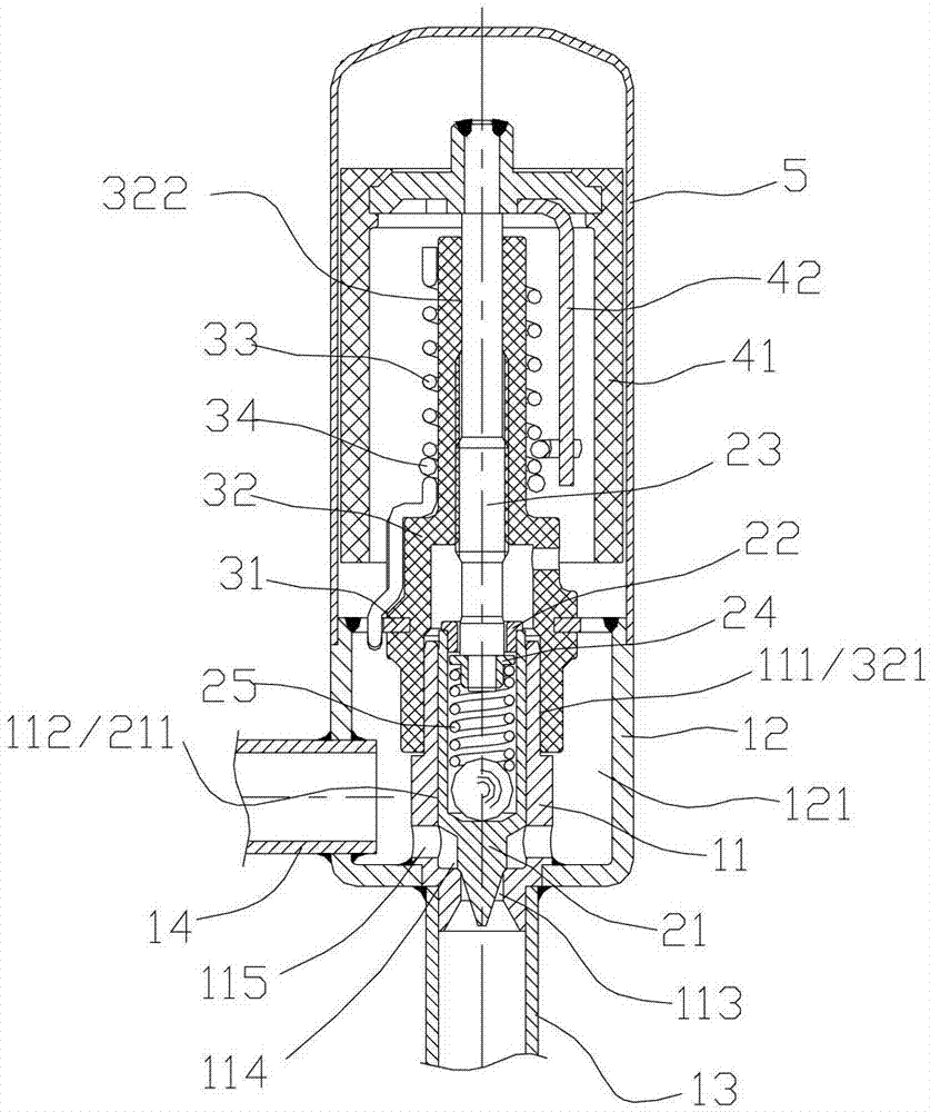
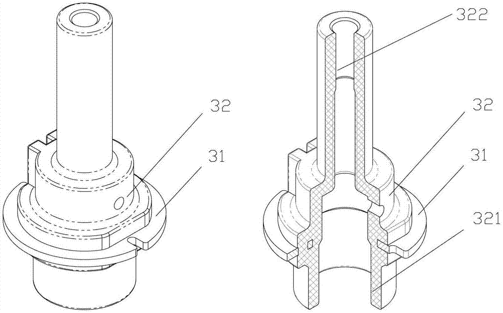
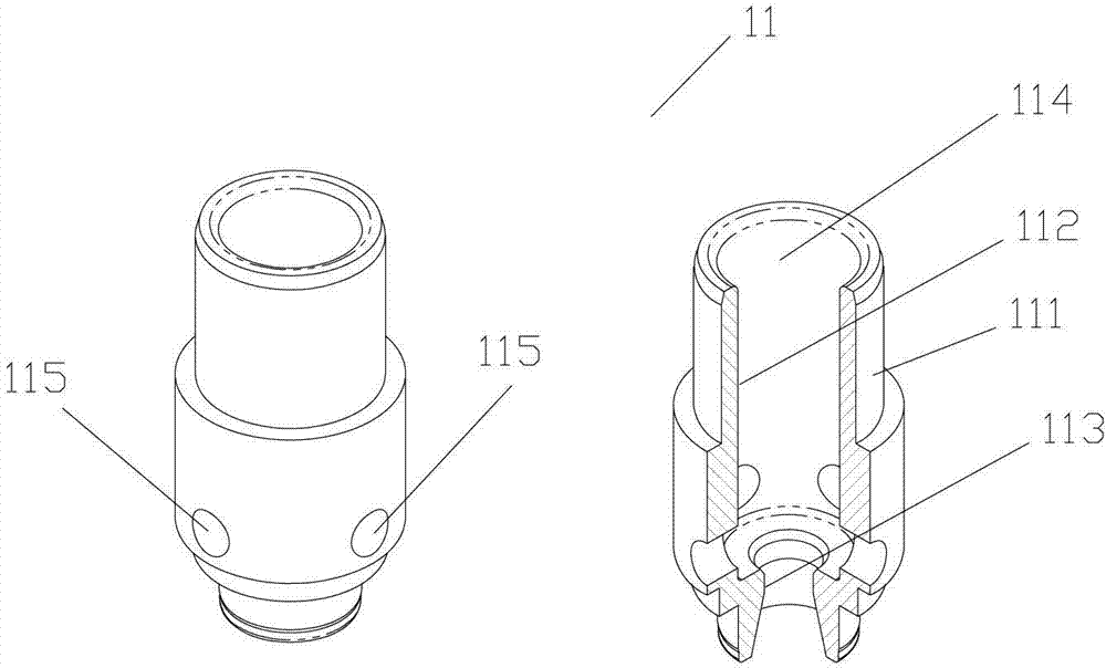
[0043] figure 1 It is a structural schematic diagram of a specific embodiment of an electric valve provided by the present invention; figure 2 It is the outline drawing and axial side sectional view of the nut assembly; image 3 It is the external view and axial cross-sectional view of the valve core seat. Please see figure 1 , figure 2 and image 3 .

[0044] The electric valve provided by the present invention includes a valve seat assembly, a nut assembly, a valve needle screw assembly and a rotor assembly.

[0045] The valve seat assembly includes a valve core seat 11 and a valve seat 12 . A valve port 113 is also processed on the valve core seat 11, and the valve seat 12 is a substantially cylindrical struct...


PUM


Abstract

An electrical valve for adjusting fluid flow comprises a valve seat (12) provided with a valve chamber (121) and a valve plug seat (11) with a valve port (113) fixed on the valve seat; a valve needle-screw stem assembly comprises a screw stem (23) and a valve needle (21) drivable by the screw stem (23); a nut assembly comprises a nut (32) and a connecting plate (31), wherein the connecting plate is fixedly connected to the valve seat, the nut thread fits the screw stem, the nut is provided with a lower pilot segment (321) thereof, the valve needle is provided with a lower pilot segment (211), and the valve plug seat is provided with a first pilot segment (111) fitting the lower pilot segment of the nut and a second pilot segment (112) fitting the lower pilot of the valve needle. The electrical valve enables concentricity between the nut and the valve needle-screw stem assembly, and concentricity between the nut and the valve port of the valve plug seat to be easily ensured, so as to prevent the problems of the valve port not being sealed tightly or the valve port being worn eccentrically, such that the operational reliability of the electrical valve is increased.

Description

[0001] This application claims priority from the following patent applications, the entire contents of which are hereby incorporated by reference into this application: [0002] 1. Submitted to the China Patent Office on October 15, 2010, with the application number 201010515234.1 and the Chinese patent application titled "An Electric Valve"; [0003] 2. On October 15, 2010, the Chinese patent application with the application number 201010515238.X and the invention name "Electric Valve and Its Stopping Device" was submitted to the China Patent Office; [0004] 3. On July 1, 2011, the Chinese patent application with the application number 201110184918.2 and the title of the invention "an electric valve device" was submitted to the China Patent Office. technical field [0005] The invention relates to the technical field of control valves, in particular to an electric valve for regulating fluid flow. Background technique [0006] In air conditioners, refrigerators, heat pump ...

Claims


Application Information

Patent Timeline
Patent Type & Authority Patents(China)
IPC IPC(8): F16K31/04F16K1/42
CPCF16K31/04F16K1/42
Inventor 魏先让
Owner ZHEJIANG SANHUA INTELLIGENT CONTROLS CO LTD
Why Eureka
Try Eureka