Electromagnetic valve

A solenoid valve and valve seat technology, applied in the field of solenoid valve, can solve the problems of unreliable action, increase the cost of solenoid valve, increase the diameter of iron core, etc., and achieve the effect of improving reliability

Active Publication Date: 2009-08-05
ZHEJIANG SANHUA INTELLIGENT CONTROLS CO LTD
View PDF0 Cites 12 Cited by
  • Summary
  • Abstract
  • Description
  • Claims
  • Application Information

AI Technical Summary

Problems solved by technology

[0005] Similarly, various solenoid valves in fluid environments such as water, oil, non-corrosive gas and steam also have similar problems. Due to the increase in the pressure difference between the inlet and outlet ends, the electromagnetic force provided by the coil energization is insufficient, which makes it difficult to open the solenoid valve. Or the action is unreliable. In the prior art, the method of increasing the d

Method used


Image

  • Electromagnetic valve
  • Electromagnetic valve
  • Electromagnetic valve

Examples


Embodiment 1

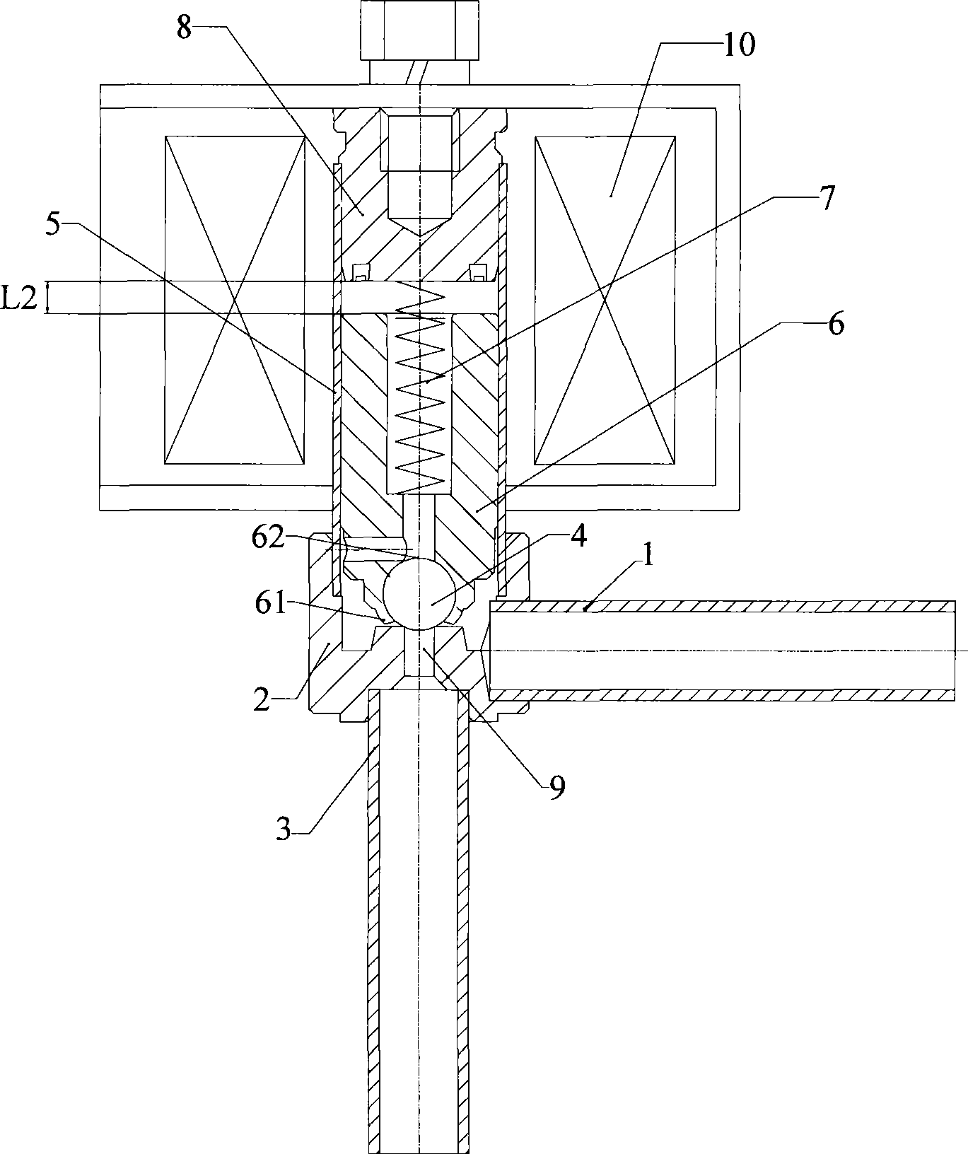
[0041] This embodiment discloses a solenoid valve structure in which the sealing member is a ball type as a preferred specific implementation manner. The following is attached Figure 3 to Figure 5 Be explained.

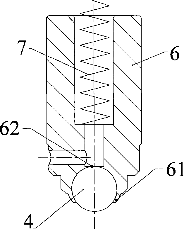
[0042] image 3 It is a schematic diagram of the structure of the solenoid valve in this embodiment when it is in a closed state, Figure 4 It is a schematic diagram of the local structure of the steel ball leaving the valve port in this embodiment, Figure 5 It is a schematic diagram of the partial structure of the moving iron core and the static iron core in this embodiment.

[0043] Such as image 3 As shown, the solenoid valve in this embodiment includes: a valve seat 2, a sleeve 5 connected to the valve seat 2 and a coil 10 outside the sleeve 5, the coil 10 is energized or de-energized to control the opening or closing of the solenoid valve, and the valve seat 2 There is a valve port 9 and the medium inlet pipe 1 and outlet pipe 3 are welded and fixed, the in...

Embodiment 2

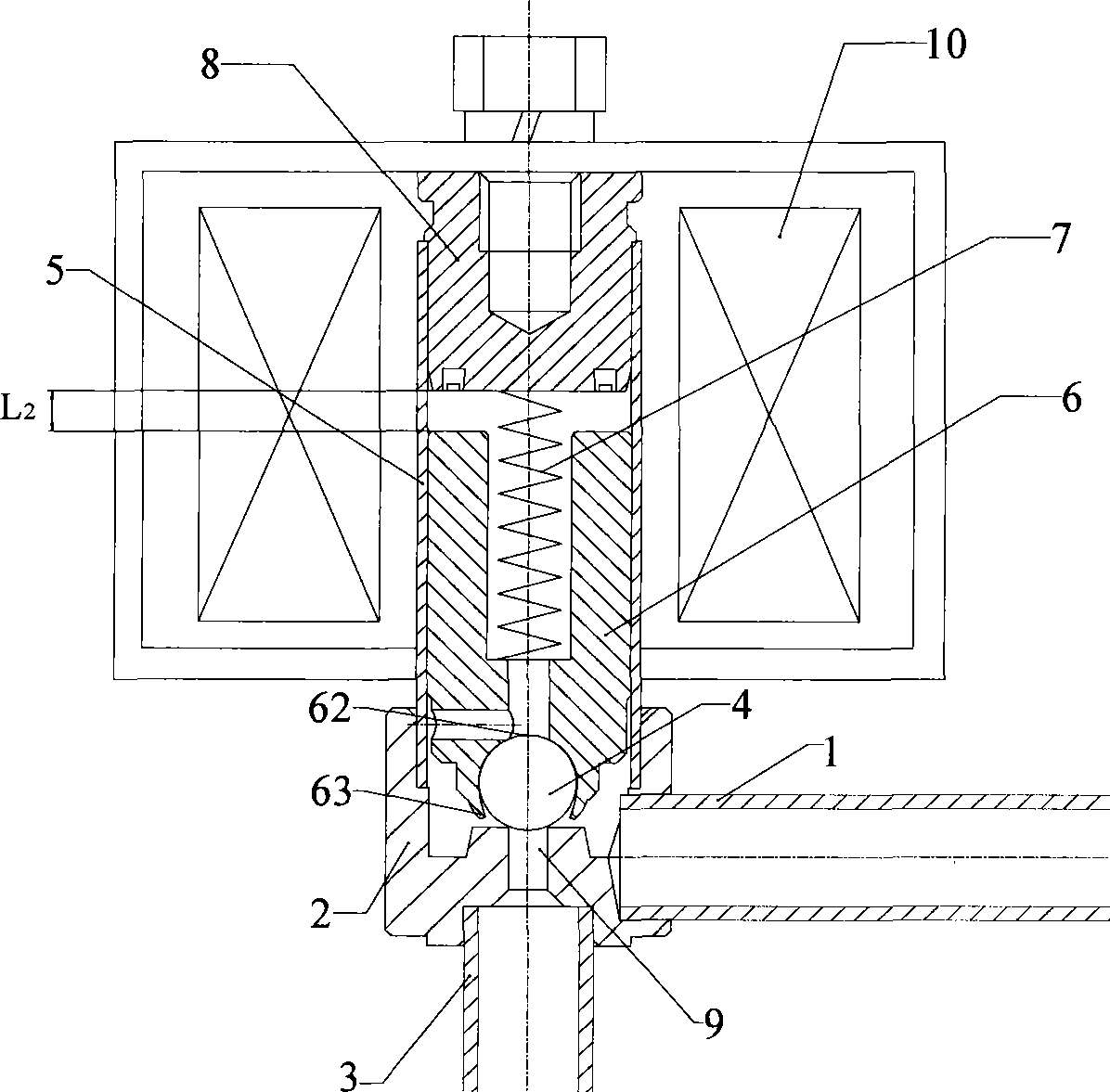
[0051] This embodiment combines Figure 6 , Figure 7 , Figure 8 A more preferred embodiment is disclosed, Figure 6 It is a schematic diagram of the decomposition structure of the moving iron core in this embodiment, Figure 7 yes Figure 6 The schematic diagram of the overall structure of the moving iron core, Figure 8 It is a structural schematic diagram of the closed state of the solenoid valve in this embodiment.

[0052] The difference from the foregoing embodiments is that the moving iron core 6' includes two parts: a soft magnetic permeable body 68 and a non-magnetic seal fixing part 69, the magnetic permeable body 68 is made of soft magnetic materials, and the seal fixing part 69 is made of Composed of non-magnetic materials.

[0053] Such as Figure 6 and Figure 7 As shown, the magnetic conduction body 68 and the seal fixing part 69 are press-fitted into one body through interference fit. After press-fitting, the end face 682 of the magnetic conduction bod...

Embodiment 3

[0059] Further, in order to more reliably ensure the tight connection between the magnetically permeable body 68 and the seal fixing part 69 in the above-mentioned second embodiment, a groove 683 can be provided on the outer surface of one end of the magnetically permeable body 68, and the seal A protrusion 693 is provided on the inner surface of the fixing portion 69 , so that the groove 683 cooperates with the protrusion 693 to fix. This embodiment combines Figure 9 Disclosed is a matching connection mode between the magnetically permeable body of the moving iron core and the fixing part of the seal.

[0060] Figure 9 It is a structural schematic diagram of the moving iron core described in this embodiment. Such as Figure 9 As shown, a groove 683 is provided on the outer surface of one end of the magnetic conduction body 68. After the seal fixing part 69 is pressed into the magnetic conduction body 68, the seal fixing part 69 and the magnetic conduction body 68 are pre...


PUM


Abstract

The invention discloses an electromagnetic valve, comprising a valve base (2), a sleeve (5) connected with the valve base (2), and a coil (10) outside the sleeve (5). The valve base (2) is provided with a valve opening (9) and is fixed with a medium inlet pipe (1) and a medium outlet pipe (3); a static iron core (8) and a movable iron core (6') are arranged in the sleeve (5), a spring is arranged between one end of the movable iron core (6') and the static iron core (8), a containing part (62') and an end part (63') are arranged at the other end of the movable iron core (6'), the containing part (62') contains a sealing element (4) that opens or closes the valve opening (9), and a gap is arranged between the end part (63') and the sealing element (4). In the invention, the reliable operation of the electromagnetic valve is guaranteed without increasing the diameter of the iron core or the cost.

Description

technical field [0001] The invention relates to the mechanical field, in particular to an electromagnetic valve. Background technique [0002] Solenoid valves are widely used in hydraulic, vacuum, gas transmission and refrigeration systems, and play an important role in realizing automatic control of pipelines. [0003] Take the solenoid valve in the refrigeration system as an example, figure 1 It is a schematic diagram of the internal structure of a solenoid valve commonly used in air conditioners when it is in a closed state. Such as figure 1 As shown, it includes: inlet pipe 1, valve seat 2, outlet pipe 3, steel ball 4, casing 5, moving iron core 6, spring 7, static iron core 8, valve port 9 and coil 10; where inlet pipe 1 and The outlet pipe 3 meets the valve seat 2, the sleeve 5 is connected to the valve seat 2, the coil 10 is located outside the sleeve 5, and inside the sleeve 5 are the static iron core 8, the moving iron core 6 and the spring 7 between them. When ...

Claims


Application Information

Patent Timeline
IPC IPC(8): F16K31/06F16K1/14
Inventor 严卫林王大闯
Owner ZHEJIANG SANHUA INTELLIGENT CONTROLS CO LTD
Why Eureka
Try Eureka