

Programmable Controllers
A programming controller and memory technology, which is applied in the direction of program control design, instruments, machine execution devices, etc., can solve the problems of no record of missing cache, no processing of reading, modifying and writing, etc., and achieve simple pipeline control Effect
- Summary
- Abstract
- Description
- Claims
- Application Information
AI Technical Summary
Problems solved by technology
Method used
Image


Examples
no. 1 Embodiment approach 》
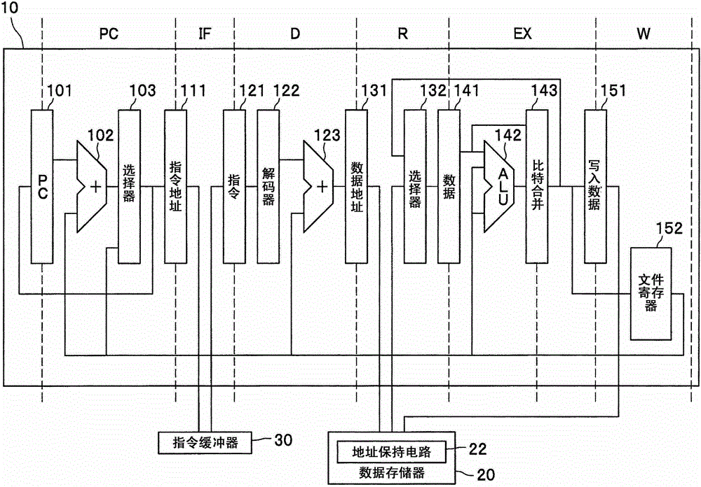
[0047] figure 1 It is a figure which shows the internal structure and pipeline structure of the bit arithmetic processor with which the programmable controller which concerns on 1st Embodiment of this invention is equipped. also, Figure 13 In order to combine the pipeline structure related to the first embodiment with Figure 14 The figure shown by comparing the prior art. Such as figure 1 as well as Figure 13 As shown, the pipeline structure involved in this embodiment consists of (1) program counter (PC) stage, (2) instruction fetch (IF) stage, (3) decoding (D) stage, (4) memory read (R) stage , (5) operation execution (EX) stage, (6) memory writing (W) stage, consisting of six stages.
[0048] The PC stage includes an adder 102 that adds the value of the PC (Program Counter) 101 indicating the address of the immediately preceding instruction to a constant "1" or a designated register value, and selects a register value indicating the result of the addition or the br...
no. 2 Embodiment approach 》
[0071] Next, the data memory 20 in the first embodiment constituted by a cache memory (refer to figure 2 ) of the second embodiment of the present invention will be described. Figure 5 It is a diagram showing the configuration of the cache memory according to the second embodiment. Such as Figure 5 As shown, the cache memory 20A as the data memory 20 is a 2-way set associative (2way set associative) type cache memory, and is configured to include an address selector 201A, index (index) holding registers 221A and 222A, and a way (way) Selector 203, write data selector 204A, path 0 tag (tag) memory 205, path 1 tag memory 206, LRU (Least Recently Used) memory 207, path 0 data memory 208, path 1 data memory 209, hit determination circuit 210 , write-back control circuit 211 , path data selector 212 , and path holding registers 213 and 214 . figure 1 The address holding circuit 22 includes an address holding circuit 1 ( 22A) having index holding registers 221A and 222A, and ...
PUM
 Abstract
Description
Claims
Application Information