Eureka AIR delivers breakthrough ideas for toughest innovation challenges, trusted by R&D personnel around the world.

Tapered roller surface defect detection system

A tapered roller and defect detection technology, which is applied in the direction of optical detection of defects/defects, sorting, etc., can solve the problem that the detection results are easily interfered by the material itself and other factors, and the air hole defects on the surface of the rolling body cannot be found, which affects the quality of detection And efficiency and other issues, to achieve the effect of convenient sorting, ensure no dead angle detection, and fast detection process

Inactive Publication Date: 2013-08-28
LUOYANG JIUDE BEARING MOLD TECH
View PDF7 Cites 31 Cited by
  • Summary
  • Abstract
  • Description
  • Claims
  • Application Information

AI Technical Summary

Problems solved by technology

[0007] In summary, there are certain defects in the use of the above-mentioned various detection methods. The manual visual inspection method requires a large number of inspection personnel, and human eyes are prone to fatigue when observing for a long time, which affects the quality and efficiency of detection; the electromagnetic eddy current detection method can be High-speed detection is easy to automate, but it is not suitable for parts with complex shapes, and can only detect surface and near-surface defects of conductive materials, and the detection results are also easily disturbed by the material itself and other factors; Smoothness is required, and experienced inspectors are required to identify the types of defects, and there is no intuition for defects; magnetic particle inspection methods cannot find pores on the surface of rolling elements, inclusions and defects hidden in the depth of welds

Method used


Image

  • Tapered roller surface defect detection system
  • Tapered roller surface defect detection system
  • Tapered roller surface defect detection system

Examples


Embodiment Construction

[0026] The present invention will be further described in detail below in conjunction with the accompanying drawings and specific embodiments.

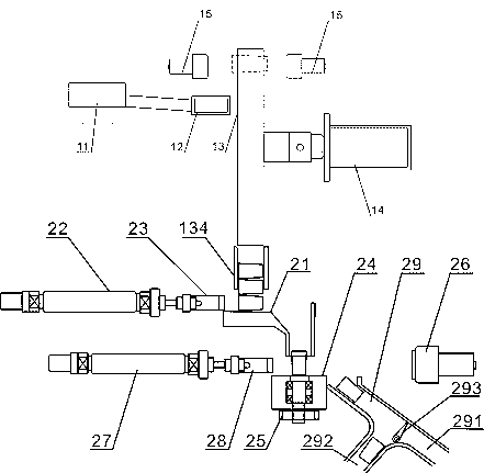
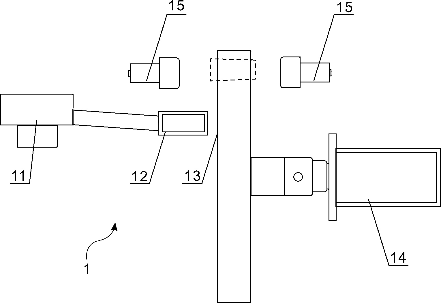
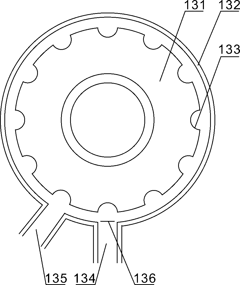
[0027] Such as Figure 1 to Figure 4 As shown, the tapered roller surface defect detection system includes a tapered roller end surface detection mechanism 1 and a side surface detection mechanism 2. The end surface detection mechanism 1 includes a feeder 12, a rotary feeder 13 and an image acquisition device II15. The rotary type The feeder 13 is provided with a through groove 133 for receiving the tapered rollers from the feeder 12, and the image acquisition device II15 is located on both sides of the rotary feeder 13, and the rotary feeder 13 is provided with a tapered roller for sorting. The first sorting mechanism for qualified products and defective products on the end face; the side detection mechanism 2 is located at the qualified product discharge port of the first sorting mechanism, and it includes positioning fixtures 21 fo...


PUM


Abstract

The invention discloses a tapered roller surface defect detection system. The tapered roller surface defect detection system comprises a tapered roller end-face detection mechanism and a tapered roller side-face detection mechanism. The tapered roller end-face detection mechanism comprises a feeder, a rotary feeder and an image acquisition device II. The tapered roller side-face detection mechanism comprises 1, a positioning clamp for vertical ordinal falling-off of tapered rollers, 2, a rotation table, 3, an image acquisition device I and 4, a sorting mechanism. The rotation table is located below an outlet of the positioning clamp and is driven by a stepping motor to rotate. One side of the rotation table is provided with the image acquisition device I and the other side of the rotation table is provided with a cylinder II. A push plate II in front of the cylinder II is corresponding to an automatic sorting table. The sorting mechanism receives qualified and unqualified tapered rollers sorted by a movable turnover panel. The tapered roller surface defect detection system effectively improves work efficiency and precision and realizes automatic production.

Description

technical field [0001] The invention relates to the field of bearing roller detection, in particular to a tapered roller surface defect detection system. Background technique [0002] The rolling body of a bearing is an important part of the bearing, and the quality of the rolling body directly affects the reliability and life of the bearing. At present, the following detection methods are mainly used for bearing rolling elements: artificial visual inspection method, electromagnetic eddy current inspection method, ultrasonic inspection method, and magnetic particle inspection method. [0003] The manual visual inspection method is to visually inspect the surface and end face of the rolling element by human eyes, and use a magnifying glass to observe whether the rolling element is flawed. [0004] The electromagnetic eddy current detection method is to pass an alternating current to a coil, and the current passing through it is constant under certain conditions. If the coil...

Claims


Application Information

Patent Timeline
IPC IPC(8): B07C5/34B07C5/02B07C5/36G01N21/88
Inventor 张亚纳郭昊卿
Owner LUOYANG JIUDE BEARING MOLD TECH
Why Eureka
Eureka Blog
Learn More