Pneumatic precise clamping device of low-rigidity thin-wall cavity part

A clamping device and cavity-type technology, which is applied in positioning devices, metal processing machinery parts, clamping, etc., can solve the problems of clamping deformation of low-rigidity thin-walled materials, and the inability to realize precise centering of workpieces and turntables. Can not solve problems such as clamping problems well, achieve reliable performance, avoid clamping deformation, and reduce error amplification

Active Publication Date: 2013-08-28
DALIAN UNIV OF TECH
View PDF9 Cites 32 Cited by
  • Summary
  • Abstract
  • Description
  • Claims
  • Application Information

AI Technical Summary

Problems solved by technology

[0003] For such special parts, the conventional clamping method is to use a three-jaw chuck with centering function to clamp the workpiece, but this method is very easy to cause deformation of the workpiece when it is applied to thin-walled parts
The patent announcement number is CN102179538, and the title is "a fixture design method and fixture device for processing low-hardness materials". In the patent, the plastic or rubber product is clamped on the fixture by widening the three-jaw chuck. Ensure that the appearance and size of the product will not be affected by the clamping method, but this method still does not get rid of the workpiece deformation caused by the clamping stress concentration in the traditional contact clamping, and this method cannot be realized on the two-dimensional workbench Precise centering of workpiece and turntable
The patent announcement number is CN101972943, and the title is "a lathe positioning fixture and clamping method for thin-walled rotary parts". In the patent, a lathe positioning fixture for thin-walled rotary parts is invented. When clamping, it is mainly subjected to axial force, the radial force is small and the force is uniform, and it has strong practicability. However, because the clamping device adopts contact clamping, it still does not solve the problem of thin-walled materials with low stiffness. Clamping deformation problem, and it is not suitable for two-dimensional two-axis turntable, and cannot provide a centering function that maintains precise concentricity with the turntable, so it cannot solve the clamping problem of this type of parts well

Method used


Image

  • Pneumatic precise clamping device of low-rigidity thin-wall cavity part
  • Pneumatic precise clamping device of low-rigidity thin-wall cavity part

Examples


Embodiment Construction

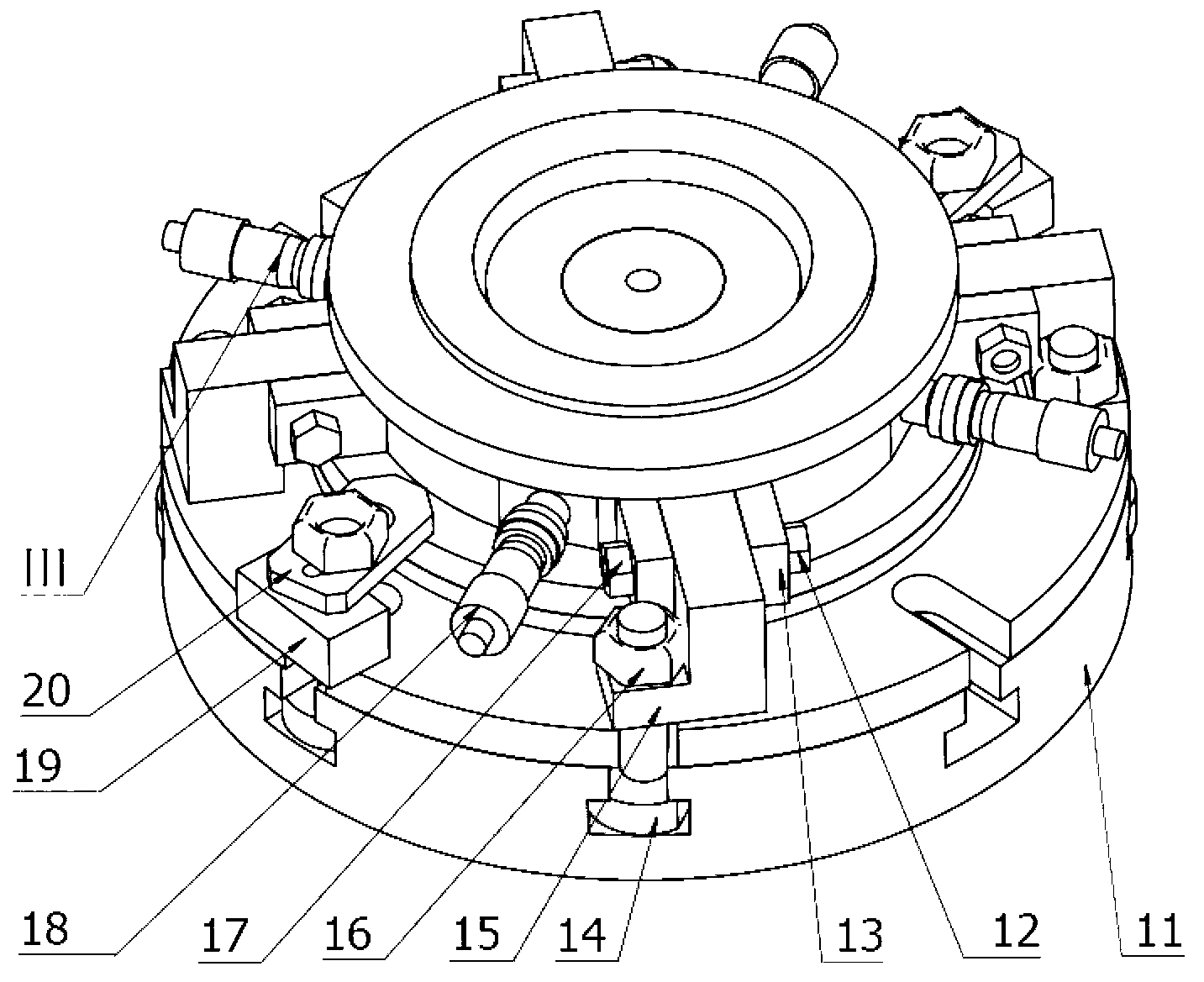
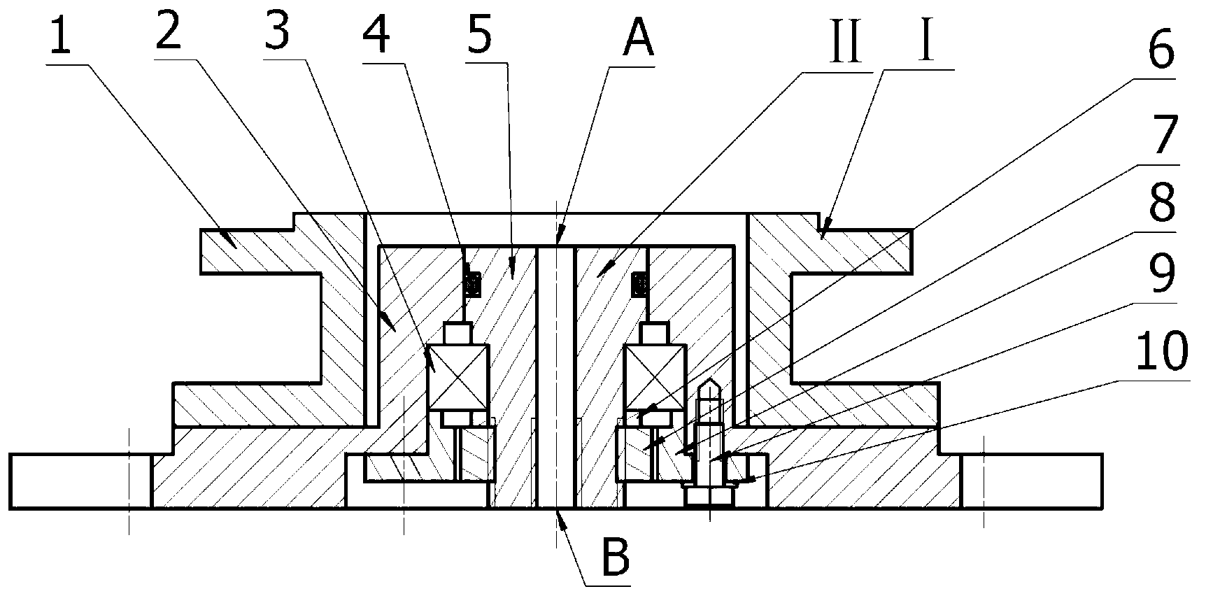
[0011] The specific implementation of the present invention will be described in detail below in conjunction with the accompanying drawings and technical solutions. The clamping device is composed of a preliminary positioning part, a pneumatic clamping part and a precision adjustment part. The preliminary positioning part can perform preliminary positioning of the workpiece and limit the degree of freedom of the horizontal direction of the workpiece. The pneumatic clamping part makes the inside of the workpiece cavity form a The vacuum environment absorbs the workpiece on the surface of the fixture, restricts the freedom of the vertical direction of the workpiece, and finally realizes the precise centering of the part by adjusting the precision feed components.

[0012] see figure 1 , figure 2 , The pneumatic clamping device of the present invention is divided into three parts: preliminary positioning part I, pneumatic clamping part II, and precision adjustment part III.

...


PUM


Abstract

The invention discloses a pneumatic precise clamping device of a low-rigidity thin-wall cavity part, belongs to the field of machining and particularly relates to a precise clamping device of a low-hardness thin-wall cavity coated part. The pneumatic precise clamping device has a function of performing reliable clamping and precise positioning on parts on a two-dimensional rotary working table and is composed of a primary positioning part, a pneumatic clamping part and a precise adjusting part. The primary positioning part is composed of an upper clamp body and a lower clamp body, the clamping part adopts the vacuum adsorption technology, and the precise adjusting part is composed of four annular supports surrounded on the lower clamp body, four spiral micro feeding mechanisms and a fixed support. The pneumatic precise clamping device integrates the clamping device and the adjusting device, performs pneumatic adjusting on clamping force according to mechanical properties of workpiece materials, and is convenient to install, compact in structure and high in centering accuracy.

Description

technical field [0001] The invention belongs to the field of mechanical processing, and in particular relates to a precision clamping device for low-hardness thin-walled cavity cladding parts. The device has the functions of reliably clamping and precise positioning the parts on a two-dimensional rotary workbench. Background technique [0002] When performing five-axis machining on the surface coating layer of thin-walled, low-rigidity, and closed-cavity parts, the workpiece needs to perform linear, rotary, and yaw motions with high acceleration and deceleration speeds and fast motion speeds. In order to keep the parts in the process of processing If there is no movement, no detachment, and no tilting in the middle, the parts tooling is required to have reliable clamping force and centering ability. At the same time, because the part itself has the characteristics of a low-rigidity thin-walled cavity, excessive clamping force will cause deformation of the part and result in ...

Claims


Application Information

Patent Timeline
Patent Type & Authority Applications(China)
IPC IPC(8): B23Q3/08
Inventor 贾振元刘巍赵凯王泠王福吉陈宇勤
Owner DALIAN UNIV OF TECH
Why Eureka
Try Eureka