Method and device for separated operation of cylinders of multi-cylinder internal combustion engine

A multi-cylinder internal combustion engine and internal combustion engine technology, applied in mechanical equipment, engine control, machine/engine, etc., can solve the problems of unsatisfactory fuel saving effect and reduction of effective power of internal combustion engine, etc., achieve significant fuel saving effect, improve combustion conditions, and reduce emissions Effect

Active Publication Date: 2013-08-28
牛刚学
View PDF4 Cites 5 Cited by
  • Summary
  • Abstract
  • Description
  • Claims
  • Application Information

AI Technical Summary

Problems solved by technology

[0003] In order to better improve the fuel-saving effect of the multi-cylinder internal combustion engine, improve the operating efficiency of the internal combustion engine, and solve the problem that when some cylinders stop working, the cylinders that stop working have large compression resistance and consume power, thereby reducing the effective power of the internal combustion engine and the fuel-saving effect is not ideal. Problem, the present invention proposes a method and device for multi-cylinder internal-combustion engine working in separate cylinders. Its realization method is: without changing the existing valve mechanism of the internal-combustion engine, an additional set of valve opening device and a program for controlling this valve opening device are added. Control integrated module, the added set of valve opening device is fixedly installed above the cylinder head. When the valve opening device works, the valve can not move to the closed position. When the piston moves up and down in the cylinder, there is no gas compression resistance in the cylinder , when all the cylinders of the internal combustion engine are working in the active state, the added valve opening device does not work, and when the cylinder corresponding to the valve opening device needs to be in a state of no gas compression resistance, the program control integrated module is directed to this cylinder The corresponding fuel supply device issues a command to stop fuel supply, and sends a working command to the valve opening device, so that there is no fuel in the cylinder and the valve is in the open state

Method used


Image

  • Method and device for separated operation of cylinders of multi-cylinder internal combustion engine
  • Method and device for separated operation of cylinders of multi-cylinder internal combustion engine
  • Method and device for separated operation of cylinders of multi-cylinder internal combustion engine

Examples


Embodiment 2

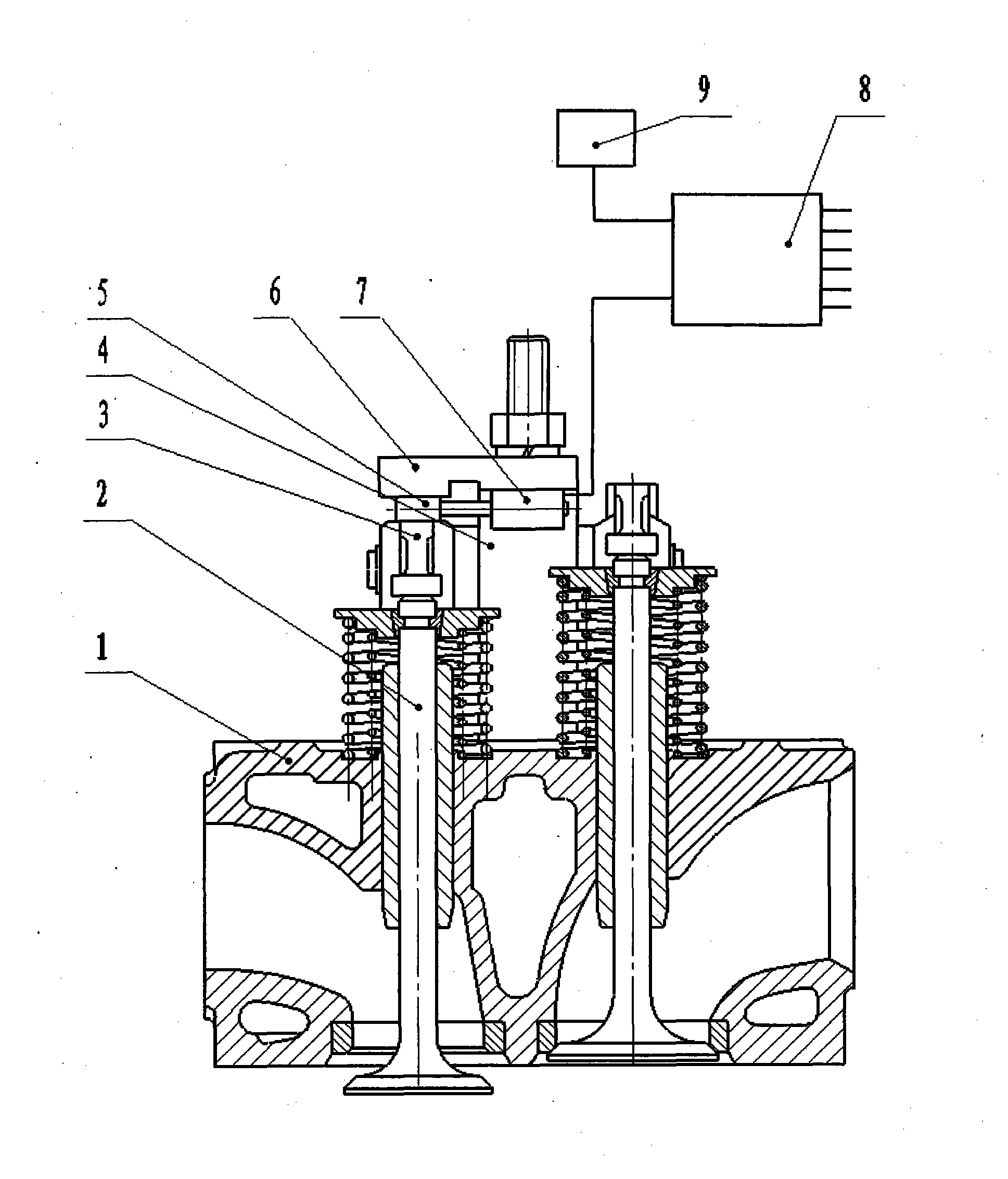
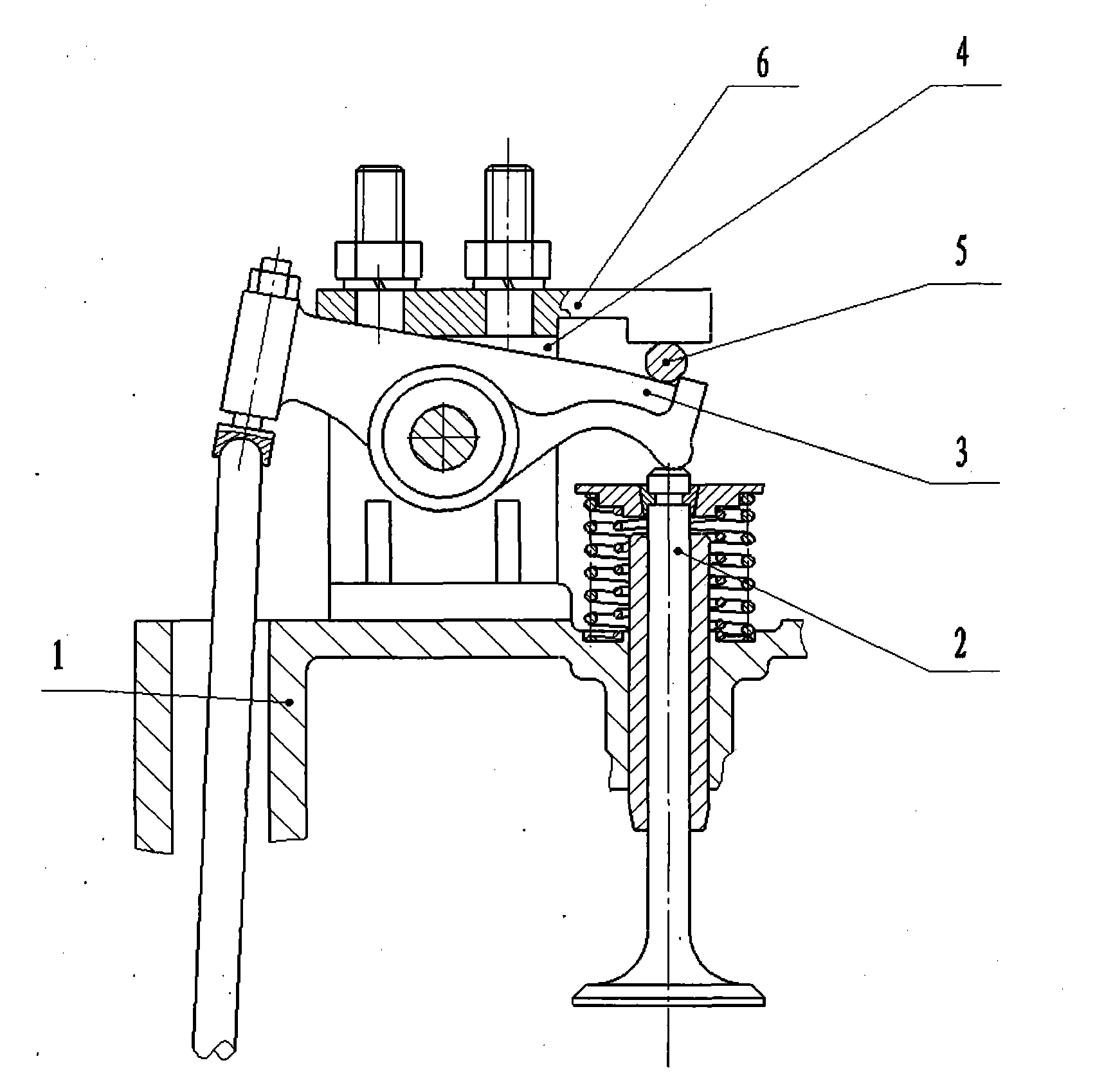
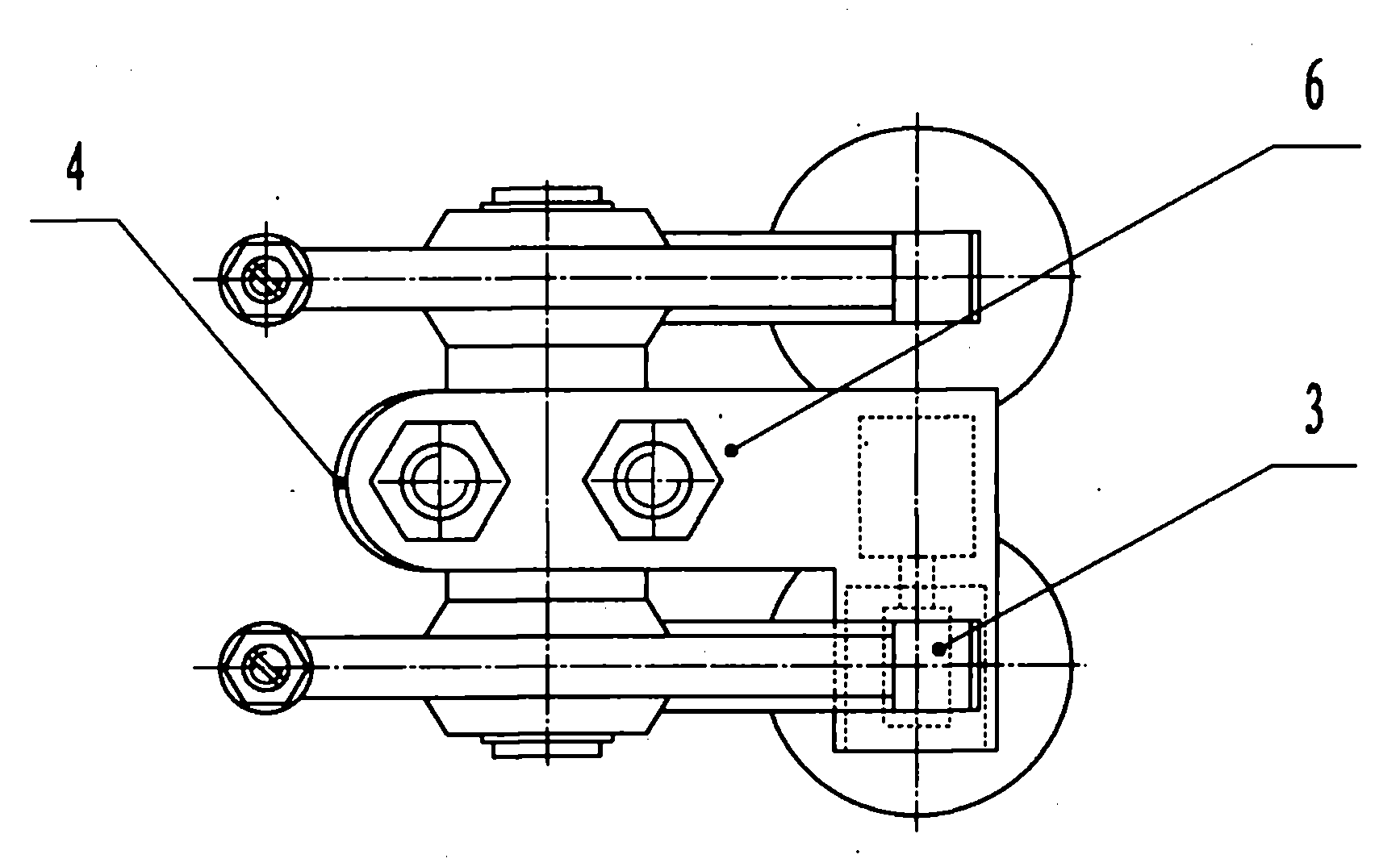
[0018] Figure 4 Among them, the upper part of the cylinder head 1 corresponds to the fixed spacer 10 under the rear part of the valve rocker arm 3, and a valve opening device is installed on one side of the spacer 10, and the valve opening device is an electromagnet 7, when all the cylinders of the internal combustion engine are used as When working in power state, the electromagnet 7 does not work. When the cylinder corresponding to the electromagnet 7 needs to be in a state of no gas compression resistance, the program control integrated module 8 sends an oil supply stop command to the oil supply device 9 corresponding to this cylinder, Send a work command to the electromagnet 7, and the oil supply device 9 stops supplying oil to this cylinder. The moving iron core 5 of the electromagnet 7 is located between the bottom of the rear part of the valve rocker arm 3 and the cushion block 10, so that the valve 2 cannot operate. In the closed position, when the piston moves up and...

Embodiment 3

[0020] Image 6 Among them, the upper part of the cylinder head 1 corresponding to the position of the valve 2 and one side of the camshaft 11 are fixedly installed with a valve opening device. The device is an electromagnet 7, and the moving iron core 5 of the electromagnet 7 is U-shaped. When all the cylinders of the internal combustion engine are When the work state is working, the electromagnet 7 does not work. When the cylinder corresponding to the electromagnet 7 needs to be in a state of no gas compression resistance, the program control integrated module 8 sends an oil supply stop command to the oil supply device 9 corresponding to this cylinder , to send a work command to the electromagnet 7, the oil supply device 9 stops supplying oil to this cylinder, and the moving iron core 5 of the electromagnet 7 is located between the valve cap 12 and the camshaft 11 above the valve 2, so that the valve 2 cannot operate In the closed position, when the piston moves up and down ...

Embodiment 4

[0022] Figure 8 Among them, the position of the upper part of the cylinder head 1 corresponding to the valve 2 and the valve chamber cover 13 are fixedly installed with a valve opening device. When the cylinder corresponding to the electromagnet 7 needs to be in a state of no gas compression resistance, the program control integrated module 8 sends an instruction to stop oil supply to the oil supply device 9 corresponding to this cylinder, and sends a work instruction to the electromagnet 7, and the oil supply device 9 Stop supplying oil to this cylinder, the force of the moving iron core 5 of the electromagnet 7 makes the valve 2 move downward, and the valve is in an open state. When the piston moves up and down in the cylinder, there is no gas compression resistance in the cylinder. There is no fuel and the valve is open.


PUM


Abstract

The invention discloses a method and a device for separated operation of cylinders of a multi-cylinder internal combustion engine. The method and the device are characterized in that the method and the device are implemented by unchanging an existing valve mechanism of the internal combustion engine and additionally arranging a valve opening device and a program control integration module for controlling the valve opening device. When the cylinder corresponding to the valve opening device needs to be in the gas compression resistance free state, the program control integration module sends a fuel supply stopping command to a fuel supply device corresponding to the cylinder and an operation command to the valve opening device, so that the cylinder is in the fuel-free and valve opening state, and further, fuel is saved while emission is reduced.

Description

technical field [0001] The method and device for cylinder-by-cylinder operation of a multi-cylinder internal combustion engine of the present invention relate to the technical field of internal combustion engines, in particular to the technical fields of fuel supply systems and intake and exhaust systems of internal combustion engines. Background technique [0002] When the internal combustion engine with four cylinders or more than six cylinders is running at low power, all the cylinders are working. This situation obviously causes a waste of fuel. At present, in order to achieve the purpose of saving fuel, people can meet the needs of operation when some cylinders work. , have taken part cylinder to stop supplying oil, and people are referred to as so-called " the method that part cylinder stops working ". This method of stopping oil supply to some cylinders has a flaw. It just stops the oil supply, while the valve train operates as usual, and the original compression stro...

Claims


Application Information

Patent Timeline
Patent Type & Authority Applications(China)
IPC IPC(8): F02D13/06
Inventor 牛刚学郑兰霞廉萌曹阳胡正涛牛锦辉
Owner 牛刚学
Why Eureka
Try Eureka