Small-flow high-pressure compact type balance valve

A balance valve and high-pressure technology, which is applied in fluid pressure actuators, fluid pressure actuator system components, servo motor components, etc., can solve problems such as shortening the service life of hydraulic cylinders, uncontrollable equipment, and damage to hydraulic cylinders. Achieve fast cleaning, sensitive response and stable work

Active Publication Date: 2013-08-28
宁波宇洲液压科技有限公司
View PDF4 Cites 6 Cited by
  • Summary
  • Abstract
  • Description
  • Claims
  • Application Information

AI Technical Summary

Problems solved by technology

The hydraulic components of the balance valve in the prior art have reached a considerable level of valve sealing and self-locking functions, but if this common balance valve is installed on a very long boom cylinder, some problems may often occur An unstable condition, which can be dangerous because it can cause the equipment to become uncontrollable and operate in an unsafe condition
The use of this balance valve will also cause the hydraulic cylinder to be damaged due to frequent impact and overload, thus greatly shortening the service life of the hydraulic cylinder.

Method used


Image

  • Small-flow high-pressure compact type balance valve
  • Small-flow high-pressure compact type balance valve
  • Small-flow high-pressure compact type balance valve

Examples


Embodiment Construction

[0026] Embodiments of the present invention will be described in further detail below in conjunction with the accompanying drawings.

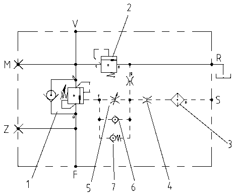
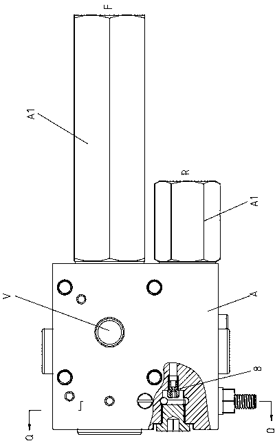
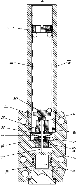
[0027] Figure 1 to Figure 10 Shown is the structural representation of the present invention.

[0028] The reference signs are: oil inlet a, oil outlet b, buffer inlet c, buffer outlet d, control input end e, control output end f, oil return end g, valve block cavity k, forward guide hole m, Small hole n, oil passage p, balance valve body A, main oil port joint A1, R port joint A2, sealing block A3, first main oil port F, second main oil port V, oil return tank port R, control Oil port S, first main oil pressure gauge port Z, second main oil pressure gauge port M, balance main valve 1, control valve block 1a, rear spring 1b, filter screen 1c, balance plate 1d, valve sleeve 1e, valve core 1f, spring seat 1g, front spring 1h, pressure adjustment screw 1i, connecting rod 1j, buffer valve 2, buffer valve sleeve 2a, buffer valve core 2b, valve co...


PUM


Abstract

The invention discloses a small-flow high-pressure compact type balance valve which comprises a balance valve body. A balance main valve, a buffer valve and a leading oil-way control system are integrated inside the balance valve body, a first main oil opening, a second main oil opening, an oil returning box opening and a control oil opening are formed in the balance valve body in a matched mode, two oil openings of the balance main valve are communicated with the first main oil opening and the second main oil opening respectively, two oil openings of the buffer valve are communicated with the second main oil opening and the oil returning box opening respectively, and the control input end of the leading oil-way control system is communicated with the control oil opening. A filter and a first damping are installed on the control input end in a series mode, the control output end of the leading oil-way control system is communicated with a control cavity of the balance main valve, and the control output end is formed by a tail port of a leading valve set composed of an adjustable throttling device, a forward direction one-way valve and a reverse direction adjustable one-way valve. A front port of the leading valve set is in tandem connection to an outlet of the first damping, the front port of the leading valve set is connected with a second damping, and the oil returning end of the second damping is communicated with the oil returning box opening.

Description

technical field [0001] The present invention relates to a hydraulic valve technology, in particular to a hydraulic balance valve used to control the movement of the long arm of a concrete pump truck and a concrete vehicle-mounted pump truck, specifically a compact balance valve with small flow rate and high pressure. Background technique [0002] In modern construction machinery, construction machinery and other engineering equipment, the hydraulic load-bearing system has become the main application object, and the balance valve is the key hydraulic component of this type of system, and its performance directly affects the performance of the whole machine. With the development of the national economy and the increasing difficulty of the current hydraulic machinery industry, as well as the customer's requirements for the performance and functional diversity of the balance valve have reached a new height. The hydraulic components of the balance valve in the prior art have reac...

Claims


Application Information

Patent Timeline
Patent Type & Authority Applications(China)
IPC IPC(8): F15B13/02F15B21/04F15B21/00
Inventor 卢宇邹泉敏李新缪海强
Owner 宁波宇洲液压科技有限公司
Why Eureka
Try Eureka