stack burner

A burner, stacked technology, applied in the direction of burner, gas fuel burner, combustion method, etc., can solve the problems of lack of gas and air preheating measures, insufficient combustion, insufficient combustion, etc., and achieve high energy utilization efficiency , Saving metal and high temperature resistant materials, low manufacturing cost

Inactive Publication Date: 2015-12-30
余泰成
View PDF7 Cites 0 Cited by
  • Summary
  • Abstract
  • Description
  • Claims
  • Application Information

AI Technical Summary

Problems solved by technology

The temperature during combustion is low, and the temperature of the air (oxygen) participating in the combustion is also low, resulting in incomplete combustion
[0003] Chinese patent 200720123852.5 discloses the prior art of "multi-layer superimposed honeycomb gas burner", its shortcoming is that it lacks preheating measures for gas and air, resulting in insufficient combustion

Method used


Image

  • stack burner
  • stack burner

Examples


Embodiment 1

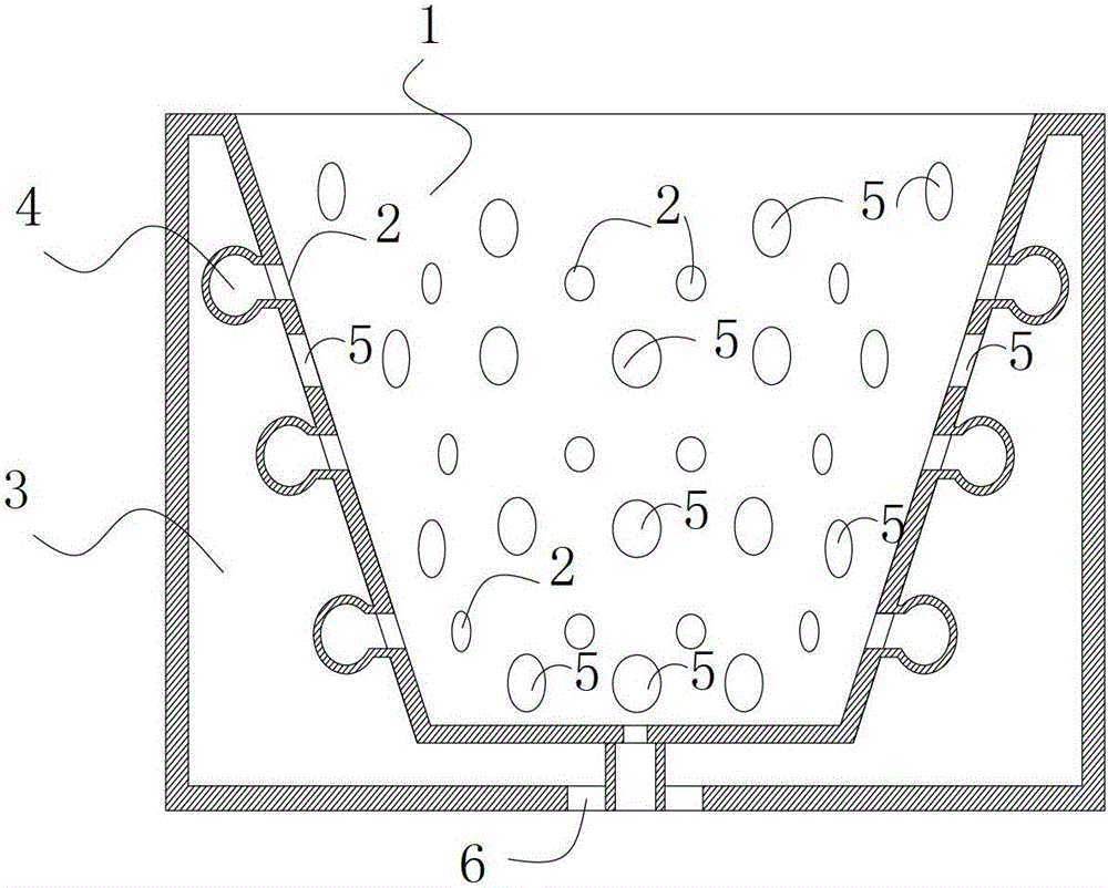
[0010] Example 1: see figure 1 .

[0011] The burner in this embodiment has a cavity-shaped combustion zone 1, and a plurality of point-shaped fuel outlets 2 are distributed in the combustion zone according to different depths. Between the inner wall of the combustion zone 1 and the outer wall of the burner is an auxiliary heating area 3, and a fuel pipeline 4 connected with a fuel outlet is arranged in the auxiliary heating area. The wall of the combustion zone 1 is provided with a plurality of through holes connecting the combustion zone and the auxiliary heating zone as air holes, and the air enters the auxiliary heating zone from the air inlet 6 at the bottom of the auxiliary heating zone to form an air passage for delivering air to the combustion zone .

[0012] The accompanying drawings are schematic diagrams, and the present invention is not limited to their proportional relationship. The introduction part of the fuel pipe in the combustor is not shown.

[0013] The...

Embodiment 2

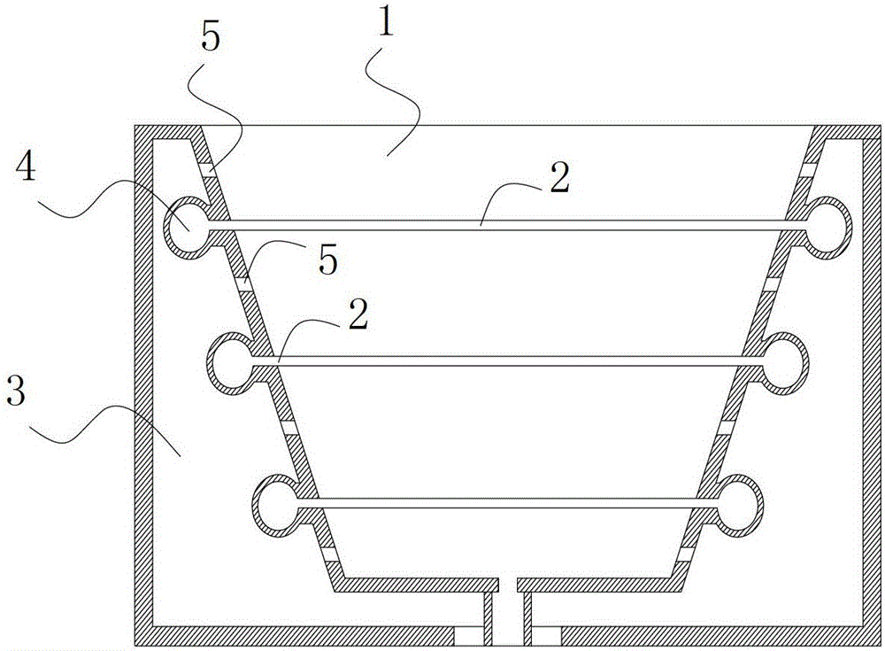
[0014] Example 2: see figure 2 .

[0015] The difference between this embodiment and Embodiment 1 is that the fuel outlet of this embodiment is a linear outlet. figure 2 Air holes are not shown.

Embodiment 3

[0017] In this embodiment, fuel pipes are arranged in a spiral shape in the auxiliary heating zone, and correspondingly, the fuel outlets in the combustion zone are point-shaped outlets arranged in a spiral shape.

[0018] In the combustion zone of the present invention, the fuel outlets are located at different depths. For non-continuous fuel outlets, such as dots (holes), the fuel outlets at the same depth are in the same layer. Even though each fuel outlet has a different depth, it is still defined by the present invention as being in a different layer. For continuous fuel outlets (linear outlets, including rings and spirals), they can be layered according to their positions in the longitudinal section. For example, a continuous helical fuel outlet, although it can be considered as only one outlet, can also constitute Multi-layer, this point is obvious to those of ordinary skill.


PUM


Abstract

The invention relates to a stack burner and relates to the field of gas stoves and gas water heaters. The stack burner comprises a sunken burning area and an auxiliary heating area. At least two layers of fuel outlets are arranged in the burning area at different depths. The auxiliary heating area is arranged between the burning area and the outer wall of the burner. Fuel tubes connected with the fuel outlets are disposed in the auxiliary heating areas. Air holes for communicating the burning area with the auxiliary heating area are formed on the wall of the burning area at different depths. The stack burner is more sufficient in fuel burning, higher in energy utilization rate and lower in production cost.

Description

technical field [0001] The present invention relates to the field of combustion. Especially in the field of gas stoves and gas water heaters. Background technique [0002] The combustion of the burner in the prior art is single-layer combustion, the fuel burns on the surface of the burner after being simply mixed with the air, and the fuel and air hardly undergo any preheating measures. The temperature during combustion is low, and the temperature of the air (oxygen) participating in the combustion is also low, resulting in incomplete combustion. [0003] Chinese patent 200720123852.5 discloses the prior art of "multi-layer stacked honeycomb gas burner", which has the disadvantage of lack of preheating measures for gas and air, resulting in insufficient combustion. Contents of the invention [0004] The technical problem to be solved by the present invention is to provide a burner with more complete combustion. [0005] The technical solution adopted by the present inve...

Claims


Application Information

Patent Timeline
Patent Type & Authority Patents(China)
IPC IPC(8): F23D14/02F23D14/66
CPCY02E20/34
Inventor 余泰成
Owner 余泰成
Why Eureka
Try Eureka