Evaporating heat exchanger

A technology of evaporative heat exchanger and tube box, which is applied in the direction of heat exchanger type, indirect heat exchanger, lighting and heating equipment, etc., can solve the problems of low heat exchange efficiency, increased system complexity, and increased production cost, etc. Achieving large capacity, reasonable and simple design, and achieving the effect of heat exchange

Inactive Publication Date: 2013-08-28
STATE GRID CORP OF CHINA +1
View PDF3 Cites 0 Cited by
  • Summary
  • Abstract
  • Description
  • Claims
  • Application Information

AI Technical Summary

Problems solved by technology

At present, the existing shell-and-tube heat exchanger is generally a one-way shell-and-tube type, and the refrigerant flowing through it is limited, so that the heat exchange efficiency is not high and the heat exchange is uneven.
Therefore, it is often necessary to use two or more heat exchangers, which not only increases the production cost, but also increases the complexity of the system, which is very inconvenient in a system with limited space.
At the same time, it is impossible to increase or decrease the refrigerant in real time, and it is difficult to adjust the refrigerant content to an appropriate level

Method used


Image

  • Evaporating heat exchanger
  • Evaporating heat exchanger

Examples


Embodiment Construction

[0018] The present invention will be further described below in conjunction with accompanying drawing.

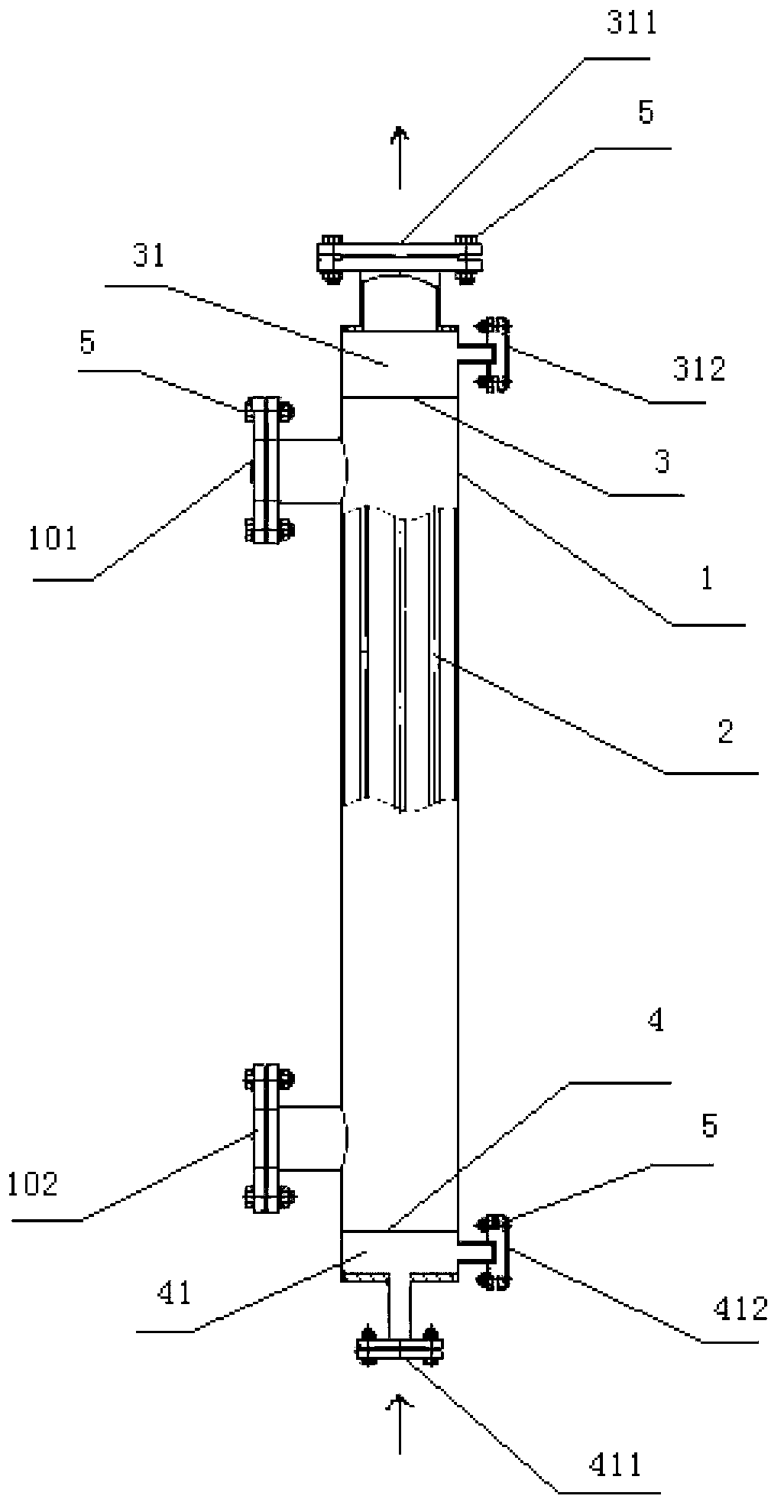
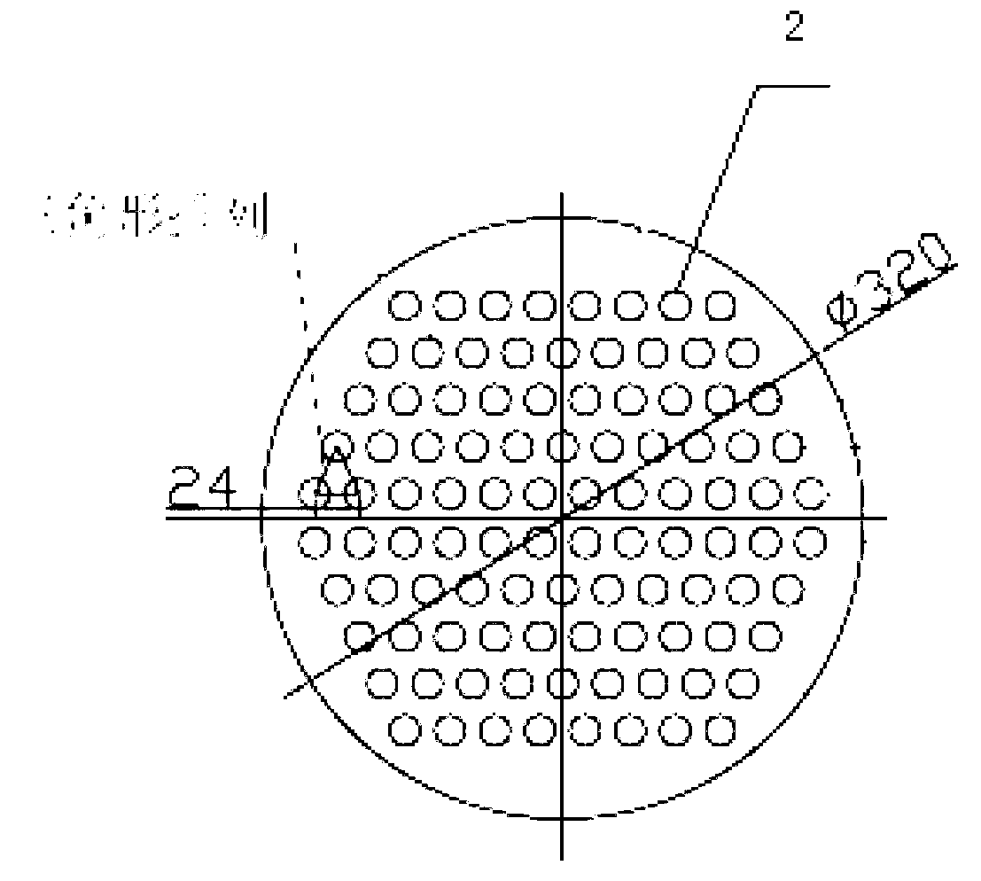
[0019] see figure 1 and figure 2 , the evaporative heat exchanger of the present invention includes a shell 1, 100 copper tubes 2, a top tube sheet 3 and a bottom tube sheet 4, wherein:

[0020] The shell 1 is cylindrical, its height is 1500mm, and its pipe diameter is Φ320mm×2.5mm, indicating that the diameter (that is, the diameter of the cross-sectional circle of the shell 1) is 320mm, and the thickness (that is, the thickness of the side wall of the shell 1) is 2.5mm, for the convenience of description, the meaning of the pipe diameter below is similar;

[0021] The top tube plate 3 divides the top part of the shell 1 into a top tube box 31, and the height of the top tube box 31 is 150 mm;

[0022] The bottom tube plate 4 divides the bottom part of the shell 1 into a bottom tube box 41, and the height of the bottom tube box 41 is 150mm;

[0023] The top of the top ...


PUM


Abstract

The invention discloses an evaporating heat exchanger. The evaporating heat exchanger comprises a cylindrical shell body, 100 copper pipes, a top portion pipe plate and a bottom portion pipe plate. The top portion pipe plate divides the top end portion of the shell body into a top portion pipe box. The bottom portion pipe plate divides the bottom end portion of the shell body into a bottom portion pipe box. The top portion of the top portion pipe box is provided with a pipe pass steam outlet. The side wall of the top portion pipe box is provided with a refrigerating fluid inlet and outlet. The bottom portion of the bottom portion pipe box is provided with a pipe pass liquid inlet. The side wall of the bottom portion pipe box is provided with a refrigerating fluid inlet and outlet. The copper pipes are respectively and vertically arranged inside the shell body and are respectively communicated with the top portion pipe box and the bottom portion pipe box. The 100 copper pipes are arranged in a triangular mode. The part, close to the side wall of the top portion pipe box, of the shell body is provided with a shell pass liquid inlet. The part, close to the side wall of the bottom portion pipe box, of the shell body is provided with a shell pass liquid outlet. The evaporating heat exchanger can achieve evenness and high efficiency of heat exchanging, and can increase and decrease the content of refrigerating fluid.

Description

technical field [0001] The invention relates to an evaporation heat exchanger. Background technique [0002] A shell and tube heat exchanger, also known as a shell and tube heat exchanger, is a partitioned heat exchanger that uses the wall of the tube bundle enclosed in the shell as the heat transfer surface. At present, the existing shell-and-tube heat exchanger is generally a one-way shell-and-tube type, and the refrigerant flowing through it is limited, so that the heat exchange efficiency is not high and the heat exchange is uneven. Therefore, it is often necessary to use two or more heat exchangers, which not only increases the production cost, but also increases the complexity of the system, which is very inconvenient in a system with limited space. At the same time, the refrigerant cannot be increased or decreased in real time, and it is difficult to adjust the refrigerant content to an appropriate level. Contents of the invention [0003] The purpose of the prese...

Claims


Application Information

Patent Timeline
Patent Type & Authority Applications(China)
IPC IPC(8): F28D7/16
Inventor 姚建歆魏巍张洁胡旭东贲志棠范进军林俊杰卢远劼蒋大为李永光卞晖
Owner STATE GRID CORP OF CHINA
Why Eureka
Try Eureka