Lossless current detecting circuit based on digital correction

A current detection circuit, digital correction technology, applied in the direction of measuring current/voltage, using digital measurement technology to measure, measuring devices, etc., can solve the problem of low current detection accuracy

Inactive Publication Date: 2013-08-28
CHONGQING UNIV
View PDF4 Cites 16 Cited by
  • Summary
  • Abstract
  • Description
  • Claims
  • Application Information

AI Technical Summary

Problems solved by technology

The biggest disadvantage of this method is that the current detection accuracy is low, because the on-resistance R DS The value of the value varies greatly with the change of temperature, and the constant on-current will detect different drain-source voltage values ​​at different temperatures

Method used


Image

  • Lossless current detecting circuit based on digital correction
  • Lossless current detecting circuit based on digital correction
  • Lossless current detecting circuit based on digital correction

Examples


Embodiment Construction

[0017] The preferred embodiments of the present invention will be described in detail below in conjunction with the accompanying drawings; it should be understood that the preferred embodiments are only for illustrating the present invention, rather than limiting the protection scope of the present invention.

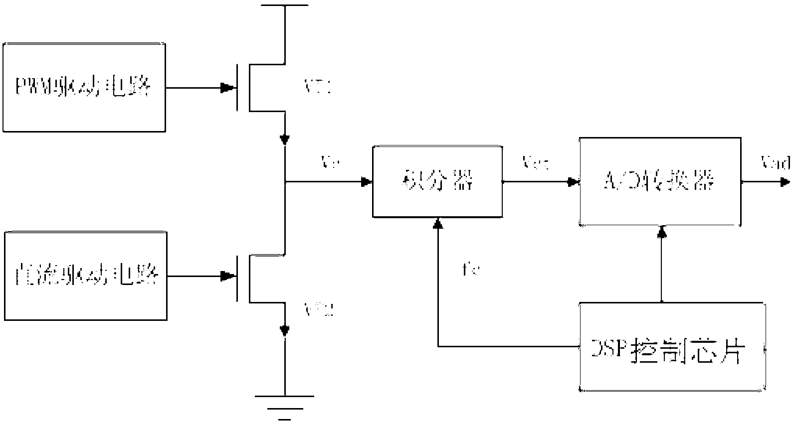
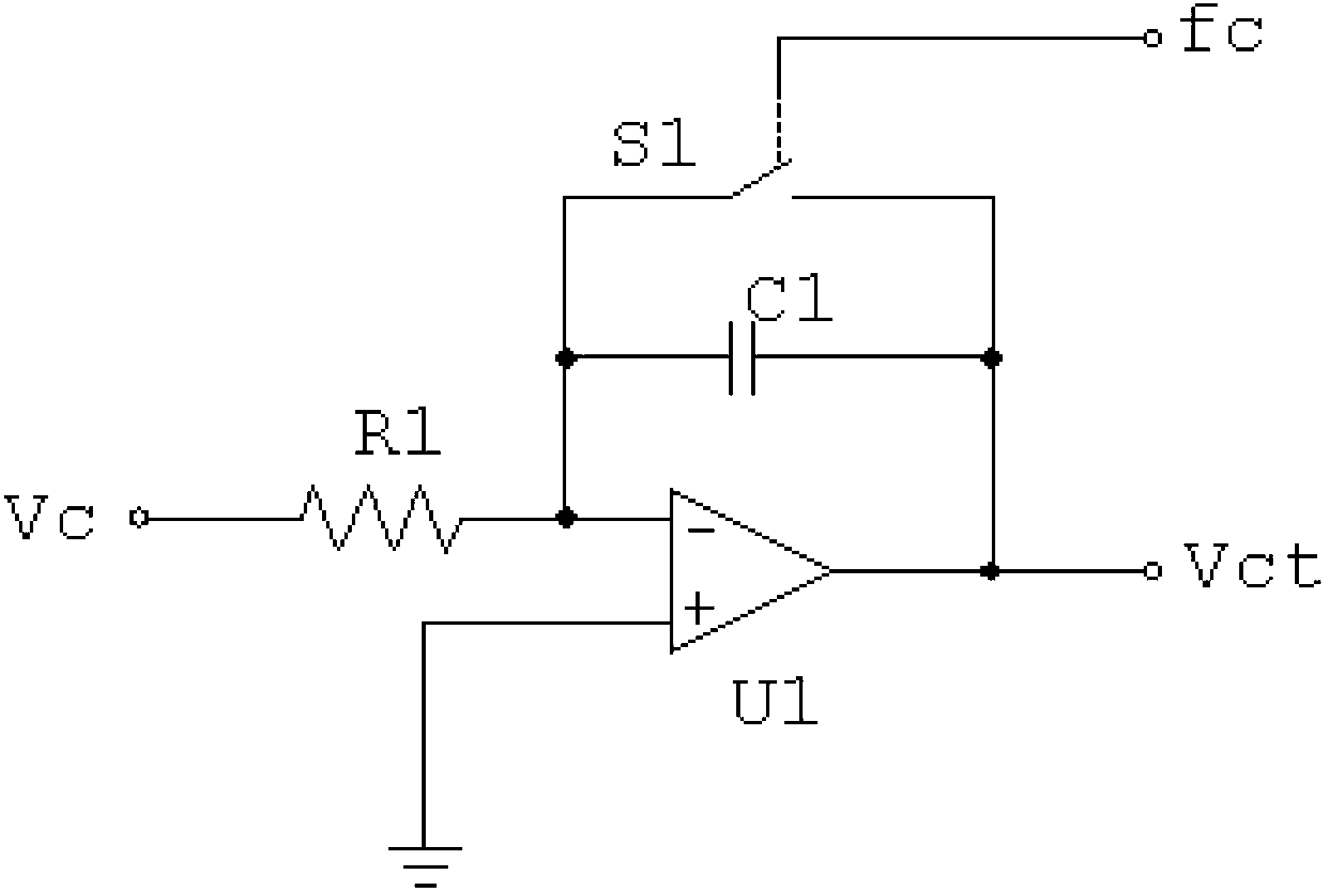
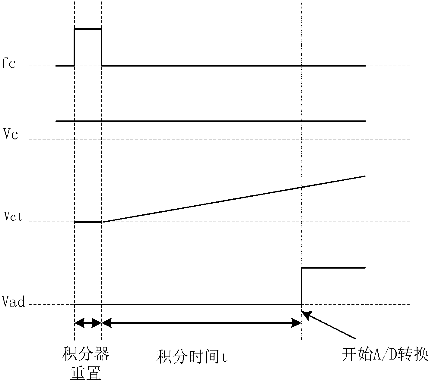
[0018] figure 1 It is a block diagram of lossless current detection based on digital correction, figure 2 is a resettable integrator, image 3 It is a timing diagram of signal work, as shown in the figure: the non-destructive current detection circuit based on digital correction provided by the present invention includes main power tube VT1, detection tube VT2, PWM drive circuit, DC drive circuit and digital correction circuit; the main power The tube VT1 is used to control the on and off of the main power circuit; the detection tube VT2 is used to detect the working current of the main power circuit; the PWM drive circuit is used to provide the driving signal for the...


PUM


Abstract

The invention discloses a lossless current detecting circuit based on digital correction. The lossless current detecting circuit comprises a main power tube VT1, a detecting tube VT2 used for detecting a working current, a PWA driving circuit, a direct current driving circuit and a digital correction circuit. The main power tube VT1 is connected with a drain electrode of the detecting tube VT2, a source electrode of the detecting tube VT2 is connected with the ground, the PWA driving circuit is connected with a grid electrode of the main power tube VT1, and the direct current driving circuit is connected with a grid electrode of the detecting tube VT2. The lossless current detecting circuit based on digital correction introduces variable gain adjustment of digital control on the basis of connecting an impedance RDS detecting current and carries out real-time on-line correction on deflection of a detected voltage value under different temperatures so as to complete high precision lossless detection of the current. The lossless current detecting circuit based on digital correction has the advantages that the digital correction circuit of gain continuous adjustment is provided, real-time correction of deflection of a connected impedance RDS detecting voltage value under different temperatures is carried out, and high precision lossless detection of the current is ensured.

Description

technical field [0001] The invention relates to the improvement of the current detection method, in particular to a non-destructive current detection circuit based on digital correction. Background technique [0002] At present, the DC / DC high-frequency switching power supply is gradually developing in the direction of low voltage, high current and high power density. The current sensing circuit is a key component of the DC / DC converter loop. All converters need to sense the input or output current for overcurrent protection. For a DC / DC converter controlled by current mode, the drive control signal of the power transistor is generated by comparing the current detection value with the output feedback voltage value, and the accuracy of current detection directly affects the conduction duty cycle of the power transistor. There are two main methods of non-destructive current detection. A structure using SENSEFET, which integrates power MOSFET and SENSEFET in parallel in the ...

Claims


Application Information

Patent Timeline
Patent Type & Authority Applications(China)
IPC IPC(8): G01R19/32G01R19/25H02M1/08
Inventor 王斌
Owner CHONGQING UNIV
Why Eureka
Try Eureka