Graphite commutator

A commutator and graphite technology, applied in the direction of current collectors, rotary current collectors, electrical components, etc., can solve the problems of small effective grasping force, low connection strength, detachment and other problems, and achieve strong effective grasping force, long service life, Stable performance

Inactive Publication Date: 2013-08-28
HUARUI ELECTRICAL APPLIANCE
View PDF5 Cites 6 Cited by
  • Summary
  • Abstract
  • Description
  • Claims
  • Application Information

AI Technical Summary

Problems solved by technology

At the same time, in the process of welding the graphite sheet and the copper commutator piece, due to the insufficient force between the graphite sheet and the copper commutator piece, the effective gripping force of the graphite sheet, the copper commutator piece and the bakelite is relatively small. , when in use, the various parts of the graphite commutator are easy to loose, which affects its service life
And the general graphite commutator in the prior art does not effectively solve the above problems
For example, Chinese Patent Publication No. CN 1723593 A, published on January 18, 2006, the name of the invention is a planar commutator. The structural innovation of welding after the contact rings are clamped without gaps effectively solves the problem of the current density distribution of the planar commutator when the conductor part is converted to the carbon part, but the ring-shaped bump of the patented carbon part is easy to transport. Brittle, and the conductor part and the carbon part are formed by welding the ring-shaped bump and the contact ring, and the connection strength is low
Another example is Chinese Patent Publication No. CN 1929216 A, published on March 14, 2007. The name of the invention is a kind of embedded graphite commutator. This patent

Method used


Image

  • Graphite commutator
  • Graphite commutator
  • Graphite commutator

Examples


Embodiment 1

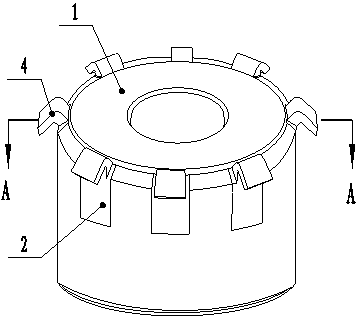
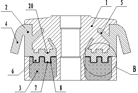
[0035] Embodiment one: combined with attached figure 1 , 2 , a graphite commutator, including bakelite 1, commutator piece 2 and graphite piece 3, bakelite 1, commutator piece 2 and graphite piece 3 are integrally injection molded, and commutator piece 2 is an "L" type structure, The inner side of the reversing piece 2 is respectively provided with a tab 5, the upper end is provided with a hook foot 4 with an outer flanging, and the lower end is provided with a pin 6, the graphite sheet 3 is completely surrounded by the bakelite 1, and is fixed with the reversing piece 2. , The graphite sheet 3 is provided with a densely formed first groove 7, the first groove 7 is consistent with the shape of the pin 6, and the tin welding fits or fits without gaps.

[0036] During production, the graphite sheet and the commutator sheet are first made into shapes, and the first groove on the graphite sheet is densified, and then the pins of the commutator sheet are pressed into the first gr...

Embodiment 2

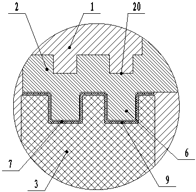
[0037] Embodiment two: combined with attached figure 1 , 2 , 3, 4, 5, a graphite commutator, comprising bakelite 1, commutator piece 2 and graphite piece 3, bakelite 1, commutator piece 2 and graphite piece 3 integral injection molding, commutator piece 2 is The "L" shape structure made of copper alloy, the inner side of the commutator piece is respectively provided with a tongue 5, the upper end is provided with a hook foot 4 with a flanging edge, the lower end is provided with a pin 6, and the upper surface of the lower end is provided with a second concave. Slot 20, graphite sheet 3 is completely surrounded by Bakelite 1, graphite sheet 3 is provided with two densely formed triangular grooves 10, pin 6 is a triangular columnar body 11 consistent with the shape of triangular groove 10, triangular groove 10 and The triangular columnar body 11 is tin-welded or gap-free, and the upper surface of the graphite sheet 3 and the triangular groove 10 are provided with a conductive ...

Embodiment 3

[0039] Embodiment three: combined with attached figure 1 , 2 , 6, 7, a graphite commutator, comprising bakelite 1, commutator piece 2 and graphite piece 3, bakelite 1, commutator piece 2 and graphite piece 3 integral injection molding, commutator piece 2 is copper metal The "L" type structure is made, the inner side of the commutator piece 2 is respectively provided with a tongue 5, the upper end is provided with a hook foot 4 with a flanging edge, the lower end is provided with a pin 6, and the upper surface of the lower end is provided with a second groove. 20. The graphite sheet 3 is completely surrounded by Bakelite 1. The graphite sheet 3 is provided with two densely formed square grooves 12. The pin 6 is a square columnar body 13 that is consistent with the shape of the square groove 12, and the square groove 12 and The square columnar body 13 is tin-welded or gap-free, and the upper surface of the graphite sheet 3 and the square groove 12 are provided with a copper fi...


PUM


Abstract

The invention discloses a graphite commutator, which comprises bakelite (1), commutator bars (2) and graphite sheets (3), and is characterized in that the bakelite (1), the commutator bars (2) and the graphite sheets (3) are injected and molded integrally; each commutator bar (2) is of an L-shaped structure; a projected bolt (5) is arranged on an inner side of each commutator bar (2); a flanging hooked pin (4) is arranged on an upper end of each commutator bar (2); an inserted pin (6) is arranged on a lower end of each commutator bar (2); the graphite sheets (3) are totally surrounded by the bakelite (1), and fixed with the commutator bars (2) to form an integral structure; and compact first grooves (7) are arranged on the graphite sheets (3), and are consistent with the inserted pins (6) in shape. According to the invention, through combination innovation of structures of the commutator bars and the graphite sheets and a connection relationship thereof, the graphite commutator with low cost, uneasy-to-damage graphite sheets, long service life, and strong effective grasping force among the graphite sheets, the commutator bars and the bakelite after forming is provided.

Description

technical field [0001] The invention relates to a commutator used in a motor, more specifically to a graphite commutator. Background technique [0002] The commutator is a part of the DC permanent magnet series motor in order to allow the motor to continue to rotate. The graphite commutator is generally composed of copper commutator, graphite sheet and bakelite powder. Milling grooves are set on the graphite sheet, the copper commutator is installed on the graphite sheet, and the bakelite powder is filled with the whole composed of graphite sheet and copper commutator sheet. Since graphite sheet is a brittle item, the edge or water chestnut of graphite sheet is brittle during transportation. At the same time, in the process of welding the graphite sheet and the copper commutator piece, due to the insufficient force between the graphite sheet and the copper commutator piece, the effective gripping force of the graphite sheet, the copper commutator piece and the bakelite is r...

Claims


Application Information

Patent Timeline
IPC IPC(8): H01R39/04
Inventor 孙瑞良史灵虎许刚位刘锦赵吉峰李国法
Owner HUARUI ELECTRICAL APPLIANCE
Why Eureka
Try Eureka