Synchronous rectification boost-buck circuit and device with parallel connection phase-shifting staggered current-sharing control

A buck-boost circuit and synchronous rectification technology, which is applied in the direction of conversion equipment without intermediate conversion to AC, can solve the problem that the buck-boost circuit is not easy to convert high-power electric energy, etc., to reduce loss and reduce energy storage requirements , to achieve the effect of overcurrent short circuit

Inactive Publication Date: 2013-08-28
SHENZHEN CESTAR ELECTRONICS TECH
View PDF4 Cites 24 Cited by
  • Summary
  • Abstract
  • Description
  • Claims
  • Application Information

AI Technical Summary

Problems solved by technology

[0012] Aiming at the above-mentioned shortcomings that the step-up and step-down circuits in the prior art are not easy to convert high-power electric energy, the present invention provides a synchronous rectification step-up and step-down circuit and device with parallel phase-shifting and interleaved current sharing control

Method used


Image

  • Synchronous rectification boost-buck circuit and device with parallel connection phase-shifting staggered current-sharing control
  • Synchronous rectification boost-buck circuit and device with parallel connection phase-shifting staggered current-sharing control
  • Synchronous rectification boost-buck circuit and device with parallel connection phase-shifting staggered current-sharing control

Examples


Embodiment Construction

[0046] This embodiment is a preferred implementation mode of the present invention, and other principles and basic structures that are the same or similar to this embodiment are within the protection scope of the present invention.

[0047] The present invention provides a synchronous rectification buck-boost circuit and device with phase-shifting interleaved parallel current sharing control, which respectively samples the inductance current of each parallel unit and provides them to their respective current controllers, and compares them with the same reference voltage after amplification so that each The peak currents of the unit inductors are evenly balanced, thereby realizing the current sharing control between parallel units. At the same time, the synchronization pulses between the controllers are phase-shifted by 90°, so that the driving pulses of each channel have a phase difference of 90°, thereby realizing the phase-shifting and interleaving control between the paralle...


PUM


Abstract

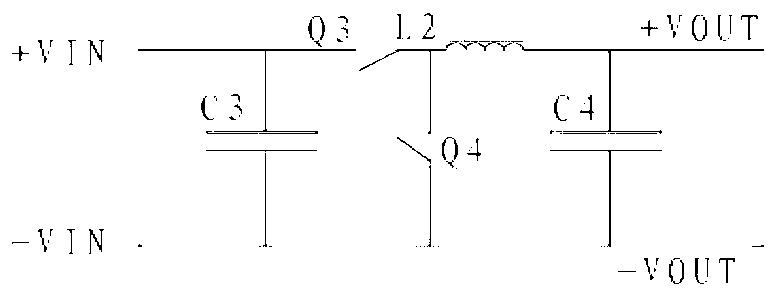
The invention discloses a synchronous rectification boost-buck circuit and device with parallel connection phase-shifting staggered current-sharing control. The synchronous rectification boost-buck circuit comprises more than one parallel-connection boost synchronous rectification circuit. Each boost synchronous rectification circuit comprises a capacitor C1, an inductor L, a current sampling point T, a switching tube Q1, a switching tube Q2 and a capacitor C2, wherein the capacitor C1 is in parallel connection at the input end, the inductor L is connected with the capacitor C1, the current sampling point T is connected at the rear end of the inductor L, the switching tube Q1 is in parallel connection between a positive pole and a negative pole of a power source, the switching tube Q2 is connected at the rear end of a current sampling point TA, and the capacitor C2 is in parallel connection at the output end. Compared with the prior art, the synchronous rectification boost-buck circuit and device achieves large-power conversion, switching frequency is multiplied due to staggered phase shifting, and peak currents of parallel-connection units are balanced and equal to one another. Due to the fact that the synchronous rectification boost-buck circuit and device has the function of parallel-connection unit synchronous rectification, loss is reduced, efficiency of the power source is improved, and compared with the size and cost of a traditional scheme, the size of the power source and cost are obviously reduced.

Description

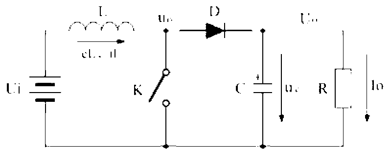
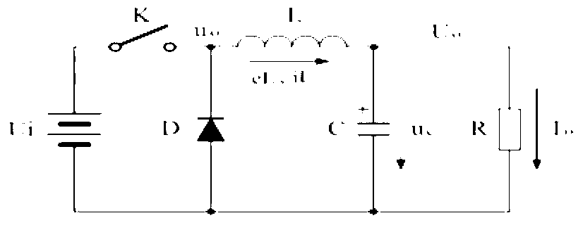
technical field [0001] The invention discloses a rectification step-up and step-down circuit, in particular a synchronous rectification step-up and step-down circuit and device with parallel phase-shifting and interleaved current sharing control. Background technique [0002] Traditional buck-boost circuit topology technology. Such as figure 1 Traditional boost topology circuits, such as figure 2 Traditional step-down topology circuit: It uses switching tubes and rectifier diodes, which have large switching losses and low efficiency, and there is no dedicated control chip to realize parallel operation. The rectifier diode D is used as the rectifier element. Since the forward voltage drop of the rectifier diode D is relatively large, a fast recovery diode is especially used in a high-voltage conversion circuit. Therefore, the switching loss is large, the heat generation is large, and the efficiency is low, and there is no dedicated control chip to realize parallel operati...

Claims


Application Information

Patent Timeline
Patent Type & Authority Applications(China)
IPC IPC(8): H02M3/10
Inventor 廉士良
Owner SHENZHEN CESTAR ELECTRONICS TECH
Why Eureka
Try Eureka