Filter failure detection device for internal combustion engine
A fault detection and filter technology, which is applied to internal combustion piston engines, exhaust devices, noise reduction devices, etc., can solve the problems of low fault detection accuracy and difficulty in detecting pressure differences, etc.
- Summary
- Abstract
- Description
- Claims
- Application Information
AI Technical Summary
Problems solved by technology
Method used
Image
Examples
Embodiment 1
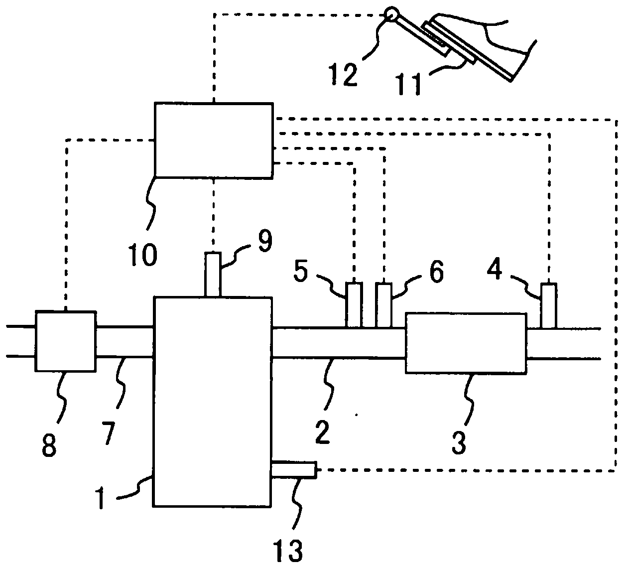
[0056] figure 1 It is a figure which shows the outline structure of the filter failure detection apparatus of the internal combustion engine of an Example. In the present embodiment, the internal combustion engine 1 is a diesel engine, but may also be a gasoline engine. The exhaust passage 2 is connected to the internal combustion engine 1 . A filter 3 for trapping particulate matter (PM) in the exhaust gas is provided in the exhaust passage 2 .
[0057] In the exhaust passage 2 downstream of the filter 3 , a PM sensor 4 for detecting the amount of PM in the exhaust gas flowing out of the filter 3 is provided. The PM sensor 4 has a pair of electrodes, and utilizes a phenomenon that the resistance between the electrodes changes according to the amount of PM adhered (deposited) between the electrodes to output a signal corresponding to the amount of PM. From this signal, the amount of PM passing through the filter 3 per unit time can be detected. In addition, the amount of P...
Embodiment 2
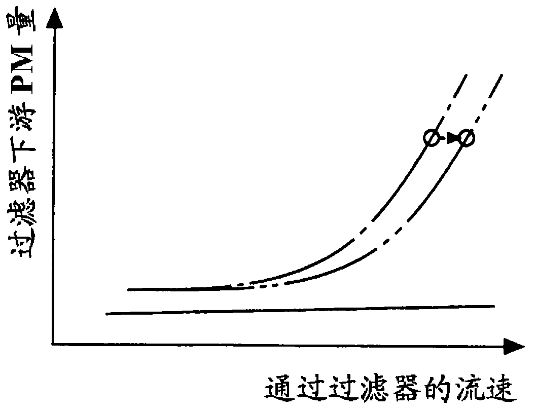
[0078] In this embodiment, the ECU 10 determines that the filter 3 is malfunctioning when the PM amount on the downstream side of the filter 3 when the flow velocity of the exhaust gas is equal to or greater than the predetermined value A is equal to or greater than the threshold value B. Other devices are the same as those in Embodiment 1, so descriptions are omitted.
[0079] Figure 5 It is a graph showing the relationship between the flow velocity of the exhaust gas passing through the filter 3 , the PM amount on the downstream side of the filter 3 , and a predetermined value A and a threshold value B. The solid line indicates the case where the filter 3 is normal, and the dotted line indicates the case where the filter 3 fails. The predetermined value A is set to a value equal to or greater than the lower limit value of the flow velocity of the exhaust gas at which a sudden change point occurs when the filter 3 fails. The predetermined value A may be set as the exhaust ...
Embodiment 3
[0093] In this example, the PM amount downstream of the filter 3 when the flow velocity of the exhaust gas is lower than the predetermined value A is compared with the amount of PM downstream of the filter 3 when the flow velocity of the exhaust gas is greater than the predetermined value A. The amount of PM, to determine whether the filter 3 failure. In addition, the predetermined value A is the same value as in Example 2. Other devices are the same as those in Embodiment 1, so descriptions are omitted.
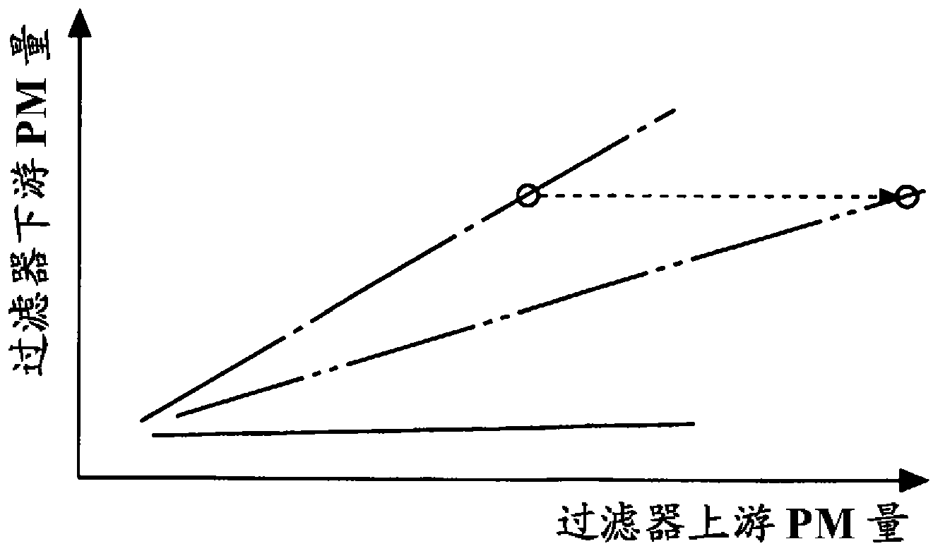
[0094] As described in Example 2, when the filter 3 fails, the PM amount on the downstream side of the filter 3 relative to the amount of change in the flow velocity of the exhaust gas when the flow velocity of the exhaust gas is equal to or greater than the predetermined value A changes become larger. On the other hand, even if the filter 3 fails, if the flow velocity of the exhaust gas is lower than the predetermined value A at a low level, the amount of PM on the downst...
PUM
 Abstract
Description
Claims
Application Information
 - R&D
- Intellectual Property
- Life Sciences
- Materials
- Tech Scout
- Unparalleled Data Quality
- Higher Quality Content
- 60% Fewer Hallucinations
Browse by: Latest US Patents, China's latest patents, Technical Efficacy Thesaurus, Application Domain, Technology Topic, Popular Technical Reports.
© 2025 PatSnap. All rights reserved.Legal|Privacy policy|Modern Slavery Act Transparency Statement|Sitemap|About US| Contact US: help@patsnap.com


