Labyrinth fly catching cage

A labyrinth and labyrinth technology, applied in the field of fly traps, can solve the problems of carrying, inconvenient use, short service life, low fly-catching efficiency, etc., achieve durable storage, low manufacturing cost, and improve fly-catching efficiency Effect

Inactive Publication Date: 2015-05-20
王好齐
View PDF5 Cites 0 Cited by
  • Summary
  • Abstract
  • Description
  • Claims
  • Application Information

AI Technical Summary

Problems solved by technology

[0003] The purpose of the present invention is to provide a fly trap with simple structure, easy operation and A labyrinth fly trap with high carrying, cleaning and fly-catching efficiency

Method used


Image

  • Labyrinth fly catching cage
  • Labyrinth fly catching cage
  • Labyrinth fly catching cage

Examples


Embodiment Construction

[0019] The present invention will be further described through the embodiments below with reference to the accompanying drawings.

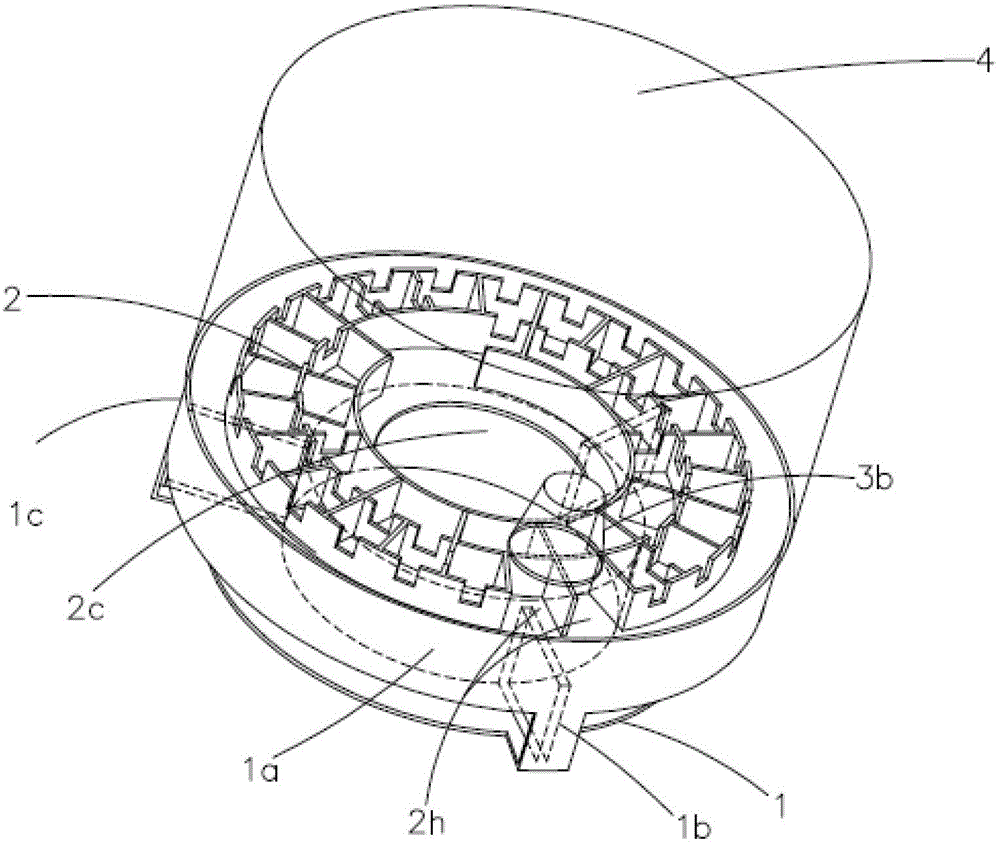
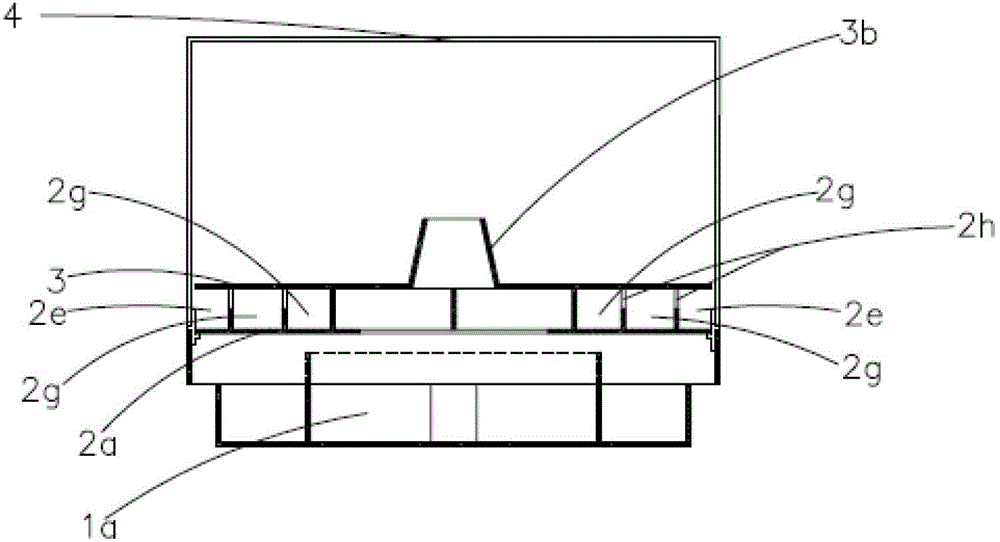
[0020] Refer to attached figure 1 to attach Figure 4 , a labyrinth flytrap, comprising a base 1, a labyrinth 2, a labyrinth cover 3 and a cage 4, the labyrinth cover 3 is placed on the labyrinth 2, the lower end of the labyrinth 2 is connected to the base 1, the The upper end of the labyrinth 2 is connected with the cage 4 .

[0021] Described base 1 comprises bait pan 1a, tripod 1b and shell 1c, and described bait pan 1a is arranged in the middle of described base 1, and described shell 1c is arranged on the periphery of described bait pan 1a, and described tripod 1b will all Said bait pan 1a is integrated with said shell 1c.

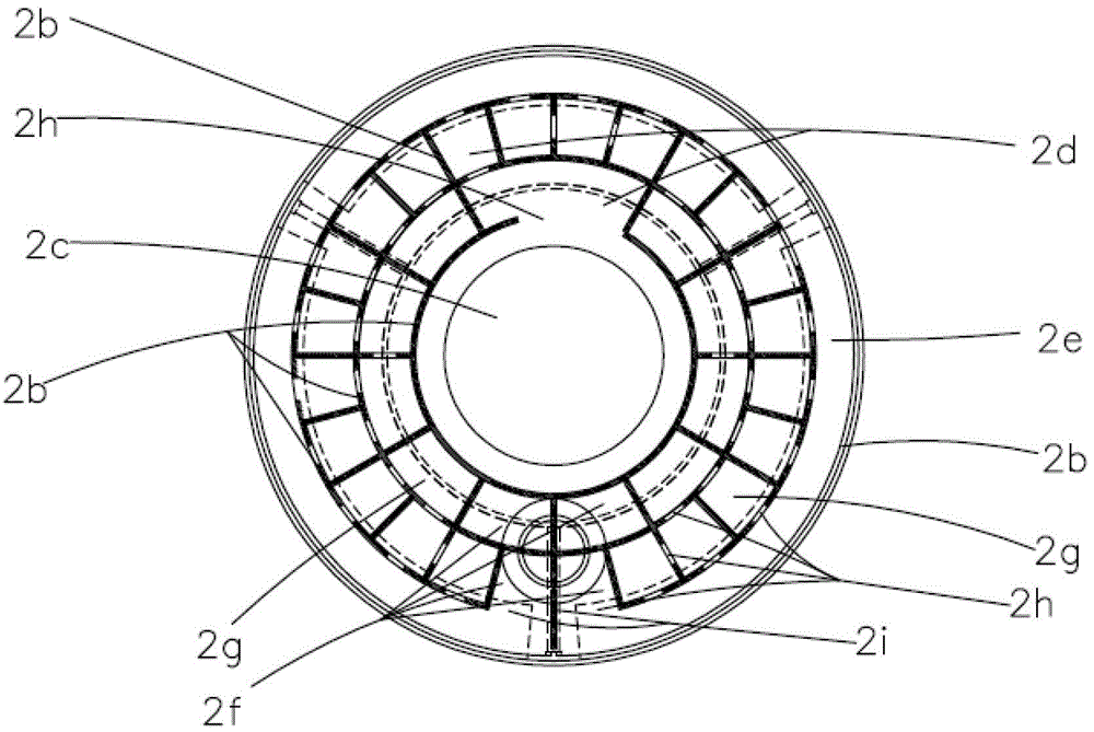
[0022] Described labyrinth 2 is disc-shaped, and it comprises labyrinth bottom plate 2a and some labyrinth partition walls 2b, is provided with the hole as maze entrance 2c in the middle of described labyrinth bottom p...


PUM


Abstract

The invention belongs to the field of fly catchers, and particularly relates to a labyrinth fly catching cage. Aiming at overcoming the defects of low efficiency, large size, inconvenience in carrying and using, short service life and inconvenience in cleaning of current traditional fly catching cages, the labyrinth fly catching cage is simple in structure, convenient to use, carry and clean and high in fly catching efficiency. The labyrinth fly catching cage comprises a base, a labyrinth, a labyrinth cover and a cage cover. The labyrinth is disposed on the labyrinth. The lower end of the labyrinth is connected with the base. The upper end of the labyrinth is connected with the cage cover. The base comprises a bait plate, foot stands and a shell. The labyrinth is of a plate shape, and comprises a labyrinth base plate and a plurality of labyrinth partitioning walls. The labyrinth cover consists of a labyrinth cover plate made of transparent materials and a labyrinth outlet tube made of transparent materials. The cage cover is made of transparent materials, and is provided with a plurality of small holes with diameters less than 3 millimeters.

Description

technical field [0001] The invention relates to a fly trap, in particular to a labyrinth fly trap. Background technique [0002] Flies are harmful insects that can spread many diseases. Fly traps have a long history as a tool for pest control and density monitoring. However, due to many technical constraints such as the diameter of the large mouth below and the small mouth above, the distance between the small mouth and the top of the cage, and the inclination angle of the horn wall of the horn of the existing traditional fly trap, the lower mouth of the horn is very large, and the upper mouth is large. The mouth is very small, and the horn body is very high, so the volume of the whole fly trap is very large, causing many inconveniences such as transportation, carrying, and use. And the cover of existing traditional fly trap is made of mosquito net material or window screen material, which is easily damaged, has a short service life, and is troublesome to clean after being...

Claims


Application Information

Patent Timeline
Patent Type & Authority Patents(China)
IPC IPC(8): A01M1/02A01M1/10
Inventor 王好齐王黎和
Owner 王好齐
Why Eureka
Try Eureka