Combined denitration method and combined denitration device for flue gas of hazardous waste incineration system

A flue gas and denitrification technology, applied in separation methods, chemical instruments and methods, gas treatment, etc., can solve problems such as difficulty in meeting nitrogen oxide emission standards, reducing the actual processing capacity of the incineration system, and reducing the service life of equipment, etc. The effect of reducing the operating cost of denitration, small changes, and reducing the amount of injection

Active Publication Date: 2016-12-14
CHONGQING CISDI THERMAL & ENVIRONMENTAL ENG CO LTD
View PDF10 Cites 9 Cited by
  • Summary
  • Abstract
  • Description
  • Claims
  • Application Information

AI Technical Summary

Problems solved by technology

At present, the discharge of pollutants in new projects of hazardous waste incineration generally adopts GB18484 "Pollution Control Standards for Hazardous Waste Incineration" or the European Union 2000 (EU2000 / 76 / EC) standard, and the process for flue gas denitrification either does not have or only uses selective non-catalysis Reduction technology (SNCR), the denitrification efficiency is not high, and it is difficult to meet the nitrogen oxide emission standards specified in the design
Since the single SNCR process only uses ammonia water or urea spray in the waste heat boiler, the utilization rate of the reducing agent is low and the operating cost is high. At the same time, the unreacted ammonia gas will escape and cause corrosion of subsequent equipment, reducing the service life of the equipment and reducing incineration. The actual processing capacity of the system

Method used


Image

  • Combined denitration method and combined denitration device for flue gas of hazardous waste incineration system
  • Combined denitration method and combined denitration device for flue gas of hazardous waste incineration system

Examples


Embodiment Construction

[0027] The preferred embodiments of the present invention will be described in detail below with reference to the accompanying drawings.

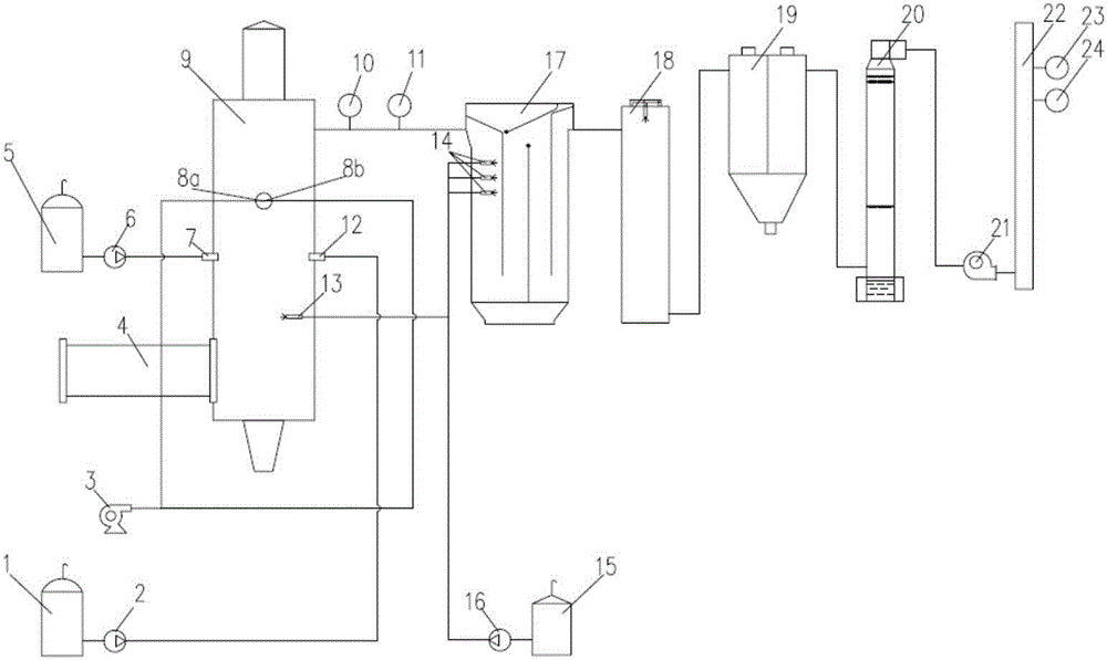
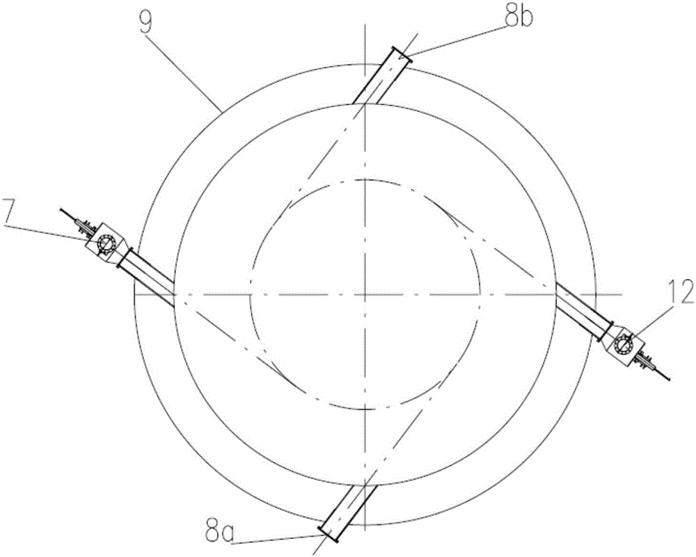
[0028] figure 1 It is a structural schematic diagram of the flue gas combined denitrification device of the hazardous waste incineration system of the present invention, figure 2 It is a schematic diagram of the plane layout of the reburning fuel spray gun in the second combustion chamber, such as figure 1 and figure 2 As shown, the device adopts a combination of organic liquid waste, light diesel reburning denitrification and selective non-catalytic reduction denitrification (SNCR). The device mainly includes: rotary kiln 4, secondary combustion chamber 9, waste heat boiler 17, quenching tower 18, bag filter 19, wet deacidification tower 20, induced draft fan 21 and chimney 22. The second combustion chamber 9 is mainly used for reburning denitration of organic liquid waste, light diesel oil and SNCR denitrification of some ammonia wat...


PUM


Abstract

The invention relates to a combined denitration method and a combined denitration device for flue gas of a hazardous waste incineration system, belonging to the technical field of flue gas denitration of industrial hazardous waste incineration systems. According to the method and the device, to-be-processed organic liquid waste and a secondary combustion chamber auxiliary fuel, namely light diesel oil are used as re-combusting fuels for carrying out graded reduction removal on NOX in flue gas by combining with the characteristics of reburning denitration and selective non-catalytic reduction (SNCR), so that the denitration efficiency can be substantially improved, the NOX in the flue gas can meet the emission standard, the utilization rate of a reducing agent can be increased, the spraying amount of ammonia water can be reduced, and the production run cost can be lowered; meanwhile, primary hazardous waste incineration system equipment is modified slightly, so that the investment is low; and the emission load of the NOX in the flue gas can be effectively reduced, and the denitration efficiency can reach about 90%, so that the method and the device have wide market promotion and use values.

Description

technical field [0001] The invention belongs to the technical field of environmental protection, in particular to the field of flue gas denitrification of industrial hazardous waste incineration systems, and relates to a combined flue gas denitrification method and device for hazardous waste incineration systems. Background technique [0002] In recent years, the demand for hazardous waste incineration and disposal in my country has been increasing day by day. According to the 2014 National Environmental Statistical Bulletin of the Ministry of Environmental Protection, by the end of 2013, the existing domestic hazardous waste incineration and disposal capacity was about 1.5 million tons, and the actual demand was close to 10 million tons. huge. At present, the discharge of pollutants in new projects of hazardous waste incineration generally adopts GB18484 "Pollution Control Standards for Hazardous Waste Incineration" or the European Union 2000 (EU2000 / 76 / EC) standard, and the...

Claims


Application Information

Patent Timeline
Patent Type & Authority Applications(China)
IPC IPC(8): B01D53/78B01D53/56
CPCB01D53/56B01D53/78B01D2258/0283B01D2251/2062
Inventor 郎明松徐志鹏
Owner CHONGQING CISDI THERMAL & ENVIRONMENTAL ENG CO LTD
Why Eureka
Try Eureka