
Drilling positioning mold based on clamping piece of transformer

A technology for clamping parts for transformers and positioning molds, which is applied to the drilling molds for workpieces and other directions, can solve the problems of large deviation of workpiece drilling positions, low production efficiency, labor-intensive and other problems, and achieves simple channel steel clamping and improved production efficiency. , The effect of accurate drilling position

Inactive Publication Date: 2013-09-04
山东沂蒙电力设备有限公司
View PDF5 Cites 3 Cited by
  • Summary
  • Abstract
  • Description
  • Claims
  • Application Information

AI Technical Summary

Problems solved by technology

[0003] In the manufacturing process of transformer clamps, the raw material channel steel is generally used to manufacture the clamps. During the manufacturing process, holes of different sizes need to be drilled in different parts of the channel steel. The most commonly used drilling method is: first, according to the position of the hole Marking on the channel steel for positioning, and then using a vise to clamp and drill the holes on the working surface of the drilling machine, this drilling method has the following problems: First, each hole must be marked and positioned, and then drilled, which is time-consuming and laborious; This process requires two people to complete the operation, which is labor-intensive. It takes a long time to mass-produce the clamps and the production efficiency is low. Third, due to manual marking and positioning, the workpiece drilling position has a large deviation

Method used


Image

  • Drilling positioning mold based on clamping piece of transformer
  • Drilling positioning mold based on clamping piece of transformer

Examples


Embodiment 1

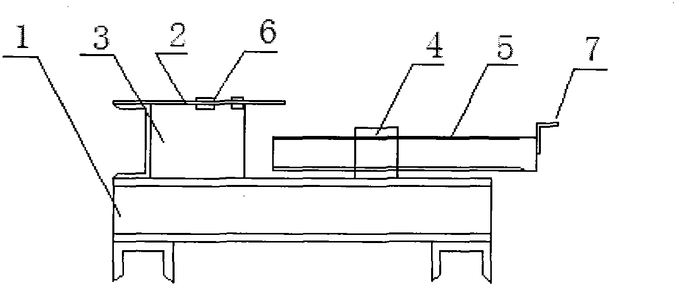
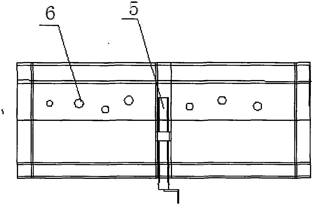
[0012] Embodiment one: if figure 1 , 2 As shown, the drilling positioning mold includes a base 1, a drill sleeve template 2, a positioning baffle plate 3, a bolt fixing seat 4, and a tightening bolt 5. The base 1 is provided with a drill sleeve template 2, a positioning baffle plate 3, and a bolt fixing seat 4. The drill sleeve template 2 is provided with a plurality of positioned drill sleeve holes 6, the bolt fixing seat 4 is provided with a jacking bolt 5, and the rear end of the jacking bolt 5 is provided with a handle 7. When in use, place the channel steel between the positioning baffle plate 3 and the jacking bolt 5 on the base 1, turn the handle 7 on the jacking bolt 5, so that the channel steel is clamped between the jacking bolt 5 and the positioning baffle plate 3 At this time, the drill sleeve hole 6 on the drill sleeve template 2 on the top of the channel steel just in time positions the drilling position of the channel steel, and the drill bit drills the channel...


PUM


Abstract

The invention discloses a drilling positioning mold based on a clamping piece of a transformer. The drilling positioning mold comprises a base, a drill bushing template, a positioning baffle board, a bolt fixing seat and an abutting bolt, wherein the drill bushing template, the positioning baffle board and the bolt fixing seat are arranged on the base, a plurality of positioning drill bushing holes are arranged on the drill bushing template, the abutting bolt is arranged on the bolt fixing seat, and a handle is arranged at the rear end of the abutting bolt. By means of the drilling positioning mold, users need not draw lines on each steel channel for positioning, so that time and labor are saved, positions for drilling holes are accurate, the steel channel is simple to clamp, only one person is required for rapidly completing the hole drilling progress, and production efficiencies are greatly improved.

Description

technical field [0001] The invention relates to a production device for transformer components, in particular to a drilling positioning mold for producing transformer clips. Background technique [0002] The clamp is used to clamp the silicon steel sheet of the iron core. At the same time, a small support plate can be welded on the clamp, and a wood piece for fixing the lead wire can be installed on the clamp. The position of the clip is on both sides of the iron core and the upper and lower iron yokes. Currently, [0003] In the manufacturing process of transformer clamps, the raw material channel steel is generally used to manufacture the clamps. During the manufacturing process, holes of different sizes need to be drilled in different parts of the channel steel. The most commonly used drilling method is: first, according to the position of the hole Marking on the channel steel for positioning, and then using a vise to clamp and drill the holes on the working surface of ...

Claims


Application Information

Patent Timeline
Patent Type & Authority Applications(China)
IPC IPC(8): B23B47/28
Inventor 徐纪华冯其同刘学文刘园杰
Owner 山东沂蒙电力设备有限公司
Learn More