Automatic crystal blank grinding and polishing system and butt joint machine thereof

A docking machine and docking machine technology, applied in grinding/polishing equipment, grinding machines, spherical grinding machines, etc., can solve the problems of increasing the waiting time of the machine, long moving stroke, and prolonging the occupation time, so as to reduce the waiting time of the machine, The effect of improving the service life of the equipment and reducing the time occupied

Active Publication Date: 2013-09-04
虞雅仙
View PDF8 Cites 3 Cited by
  • Summary
  • Abstract
  • Description
  • Claims
  • Application Information

AI Technical Summary

Problems solved by technology

[0005] The patent document with the publication number CN102366914A discloses an automatic circulation double-fixture jewelry polishing machine. The upper hemisphere grinding and polishing (front grinding and polishing) and the lower hemisphere grinding and polishing (rear grinding and polishing) of the crystal blank are carried out in the same processing cycle ( That is, fixture circulation cycle), wherein, the fixture seats on each station are arranged in parallel to the left and right along the length direction of the fixture (especially the grinding and polishing station), so that when the left and right transfer mechanism transfers the fixture between the stations, it needs to be extended first. Lift the fixture from the fixture seat of one station and then step over the fixture seat mechanism on the corresponding station, and then send it down and place it on the fixture seat of another station. Cumbersome, prone to failure and high cost
Moreover, the docking bracket (i.e. the transfer assembly part) and the waiting bracket (i.e. the fixture reset assembly part) are both 180° rotating structures in the docking mechanism, so there are the following problems: First, because the heating tube in the docking mechanism is generally High-frequency heating tubes or gas fire tubes are used, so generally the heating tubes need to be connected with high-frequency generating equipment or gas supply equipment, etc., and the heating tubes should be installed between the two docking fixtures (seats), that is, installed on the above-mentioned In the adapter assembly, frequent rotations in a wide range of 180 degrees will complicate the connection structure between the heating tube and high-frequency generating equipment or gas supply equipment, and affect the service life; secondly, in order to free up the rotation space of the adapter assembly, The wire brushes and powder discs used for cleaning the upper fixtures and dipping and gluing are set far away from the adapter assembly. Their moving strokes are long and take up a lot of time; Powder gluing and 180-degree rotation are carried out successively, which takes up a lot of time, which prolongs the time occupied by the transfer (docking) station, prolongs the waiting time of other grinding and polishing stations, and lowers the docking efficiency. Processing efficiency of automatic cycle
[0007] However, the above-mentioned structure is that the fixture seats on each station are arranged parallel to the left and right along the length direction of the fixture (especially the grinding and polishing station). Lift the fixture on the fixture seat of the station, and then step over the fixture seat mechanism on the corresponding station, and then send it down and place it on the fixture seat of another station. Such a left-right transfer mechanism is complicated in structure, cumbersome and easy Faulty and costly
In its docking mechanism, the first front and rear transfer mechanism needs to transfer the belt clamp from the docking bracket to the conversion bracket, and then wait for the conversion bracket to rotate 180 ° after the upper and lower positions are reversed, and then the first front and rear transfer mechanism will transfer the material on the conversion bracket The jig with glue is sent to the docking bracket. During this process, the first front and rear transfer mechanism reciprocates the jig, and the docking bracket can only be in a waiting state, which increases the waiting time of the machine, so further improvements are needed to increase production efficiency.

Method used


Image

  • Automatic crystal blank grinding and polishing system and butt joint machine thereof
  • Automatic crystal blank grinding and polishing system and butt joint machine thereof
  • Automatic crystal blank grinding and polishing system and butt joint machine thereof

Examples


Embodiment 1

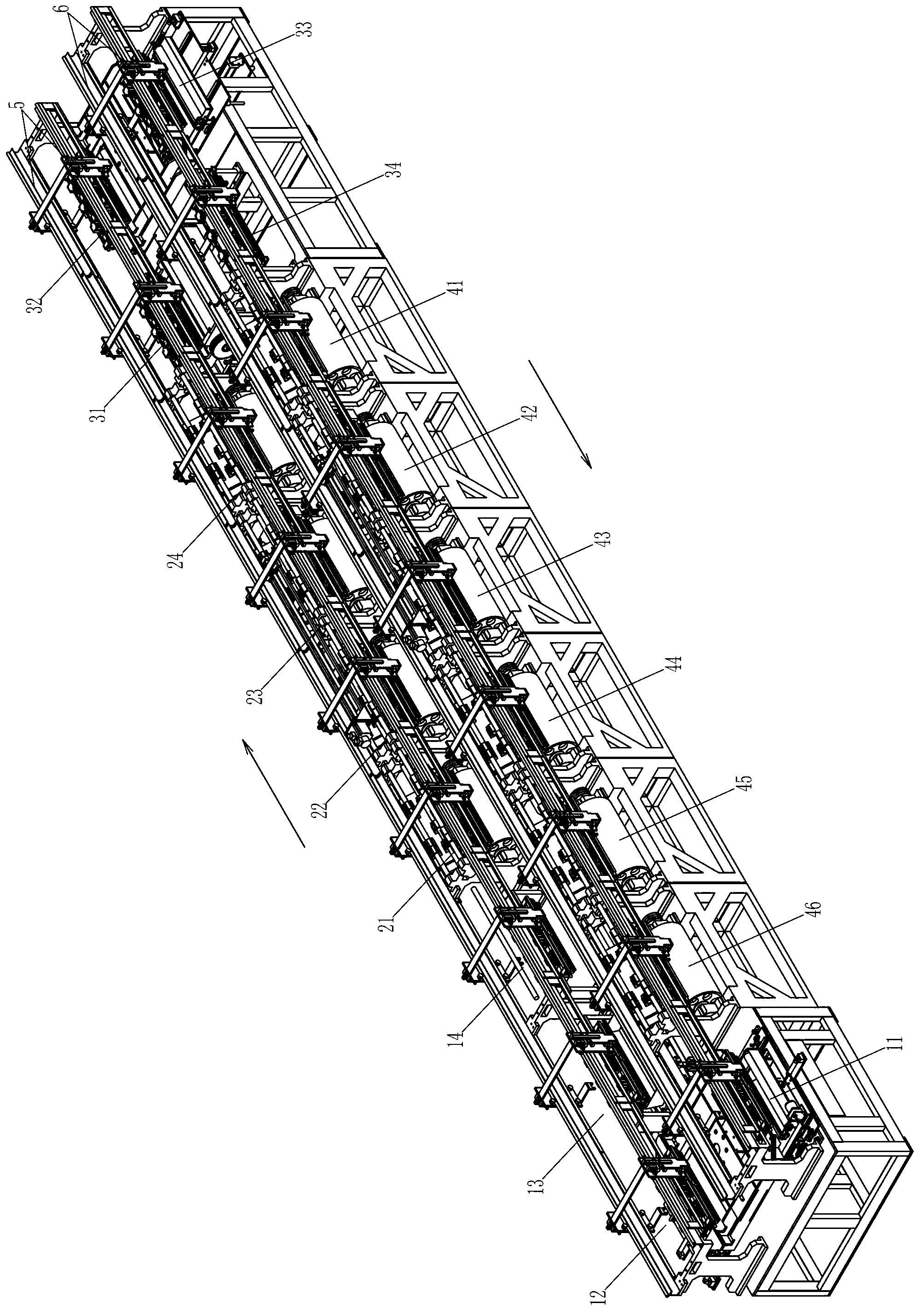
[0040] Such as figure 1 The shown automatic grinding and polishing system for crystal blanks includes a first left and right transfer mechanism 5 and a second left and right transfer mechanism 6 arranged in parallel front and back, along with the first left and right transfer mechanism 5 arranged in sequence from left to right with loading and unloading workers position (the feeding position 12, the feeding position 13, and the cooling position 14), multiple upper hemisphere grinding and polishing stations (including the upper hemisphere grinding and polishing processing primary grinding station 21, secondary grinding station 22. The first polishing station 23 and the second polishing station 24) and the docking station (wherein the docking position 31 and the cleaning position 32), along the second left and right transfer mechanism 6 are arranged in sequence from right to left with docking stations ( Among them, the docking powder dipping position 33 and the waiting position ...


PUM


Abstract

The invention discloses a butt joint machine. A rotating arm which rotates vertically is installed between a butt joint position and a waiting position, a butt joint lower fixture seat is mounted on the rotating arm, a butt joint upper fixture seat is mounted at the butt joint position, and the waiting position is vacant; when the rotating ram rotates to the butt joint position, the butt joint lower fixture seat is positioned right below the butt joint upper fixture seat, and when the rotating arm rotates to the waiting position, a fixture needle of the butt joint lower fixture seat is downward; a rotating frame which rotates horizontally is installed between a cleaning position and a butt joint powder staining position, and front and back groups of fixture seats are mounted on the rotating frame; and the fixture seats at the butt joint position and the cleaning position are laterally arranged in rows along fixture length directions, and the fixture seats at the butt joint powder staining position and the waiting position are laterally arranged in rows along fixture length directions. The invention further discloses an automatic crystal blank grinding and polishing system using the butt joint machine. According to the automatic crystal blank grinding and polishing system and the butt joint machine thereof, the structure is reasonable, actions are simple, the cost is low, the operation is reliable, and the efficiency is high.

Description

technical field [0001] The invention belongs to the field of grinding and polishing processing of crystal products, and relates to an automatic grinding and polishing system for crystal blanks for automatic grinding and polishing processing of crystal blanks, in particular to a docking machine therein. Background technique [0002] In the prior art, the automatic grinding and polishing system (grinding and polishing machine) of crystal blanks includes: a feeding station, which is provided with a feeding mechanism capable of fixing the crystal blanks on the fixture; The upper hemisphere grinding station for grinding the hemisphere and at least one upper hemisphere polishing station for polishing the upper hemisphere of the crystal blank; the docking station is provided with the ability to transfer and fix the crystal blank from a fixture to On the other fixture, a docking mechanism capable of exchanging the positions of the two fixtures; at least one lower hemisphere grinding...

Claims


Application Information

Patent Timeline
Patent Type & Authority Applications(China)
IPC IPC(8): B24B11/00B24B41/06
Inventor 虞卫东
Owner 虞雅仙
Why Eureka
Try Eureka