Workpiece positioning method in robot transportation system by means of intelligent camera

A technology of smart camera and handling system, applied in manipulators, manufacturing tools, etc., can solve the problems of high labor intensity, can not be widely used, high risk, etc., to reduce the labor intensity of personnel, shorten the production cycle, and achieve a high degree of automation. Effect

Active Publication Date: 2013-09-04
CHANGSHA CTR ROBOTICS
View PDF5 Cites 18 Cited by
  • Summary
  • Abstract
  • Description
  • Claims
  • Application Information

AI Technical Summary

Problems solved by technology

[0002] In the traditional stamping system, manual clamping or mechanical positioning are mainly used to locate or transport stamping parts. These methods cannot meet the needs of modern high-precision mass stamping production. The main reason is that manual clamping and feeding are labor-intensive , The production efficiency is low and the precision is low, and the danger is also great when encountering high-temperature stamping, and the mechanical positioning can only realize one-to-one positioning. To realize the positioning of various workpieces, corresponding various mechanical positioning structures must be provided. Such a design is complex, difficult, difficult to implement and very expensive
[0003] With the development of science and technology, the industry currently uses lasers to locate stamped parts and then uses robots to carry them. However, this method still has many defects and cannot be widely used. The main reasons are: first, the cost is high; second, it is scanned Due to the limitation of distance, the equipment is easily damaged during high temperature impact; third, for steel plates with little difference in characteristics, the scanning period is long and it is difficult to identify

Method used


Image

  • Workpiece positioning method in robot transportation system by means of intelligent camera
  • Workpiece positioning method in robot transportation system by means of intelligent camera
  • Workpiece positioning method in robot transportation system by means of intelligent camera

Examples


Embodiment Construction

[0033] The technical scheme of the present invention will be further described below in conjunction with the accompanying drawings and through specific embodiments:

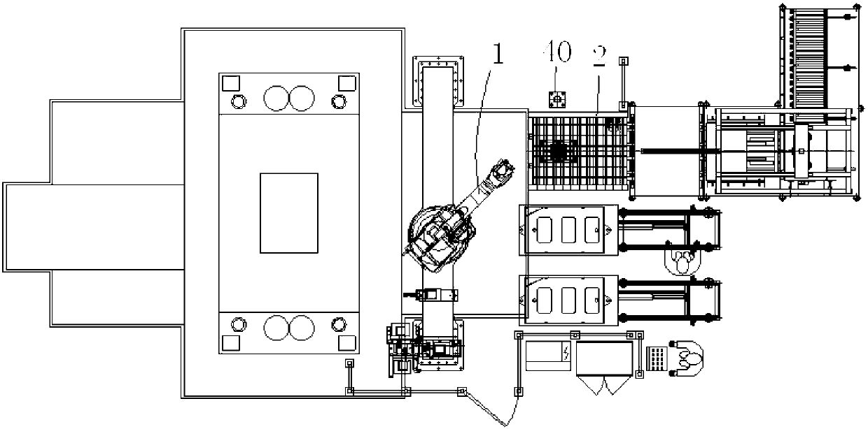
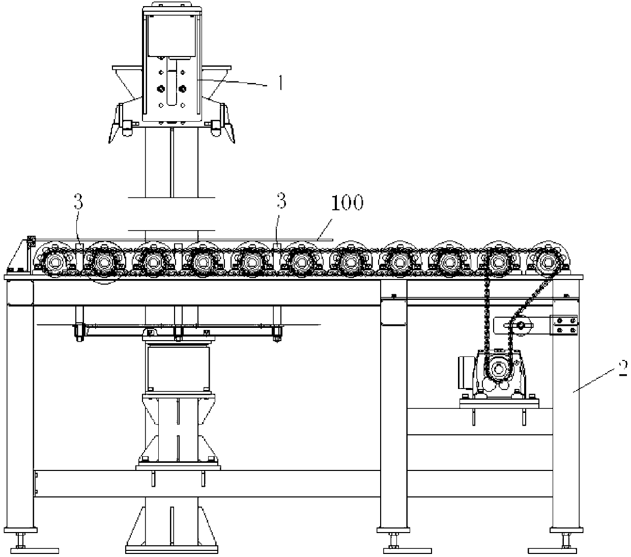
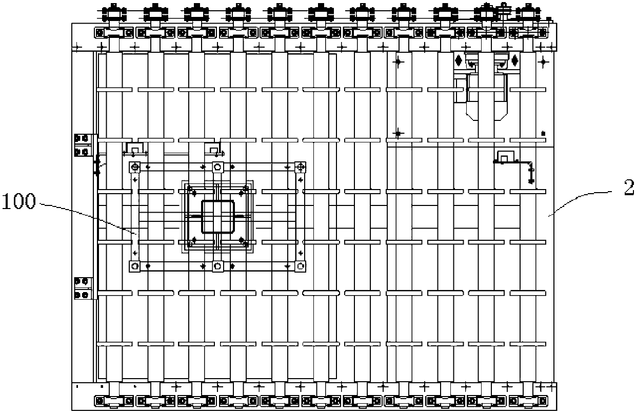
[0034] Aiming at the problems existing in the prior art, the object of the present invention is to provide a method for locating a workpiece in a robot handling system using a smart camera, which uses a combination of a smart camera 4 and a robot for automatic positioning and handling, with high degree of automation, high efficiency and It has high precision and can be applied to the needs of high-volume high-precision stamping production.

[0035] see Figure 1 to Figure 4 , the present invention provides a method for positioning a workpiece using a smart camera in a robot handling system, wherein the robot handling system includes a handling robot 1, a positioning platform 2, a push rod 3, a smart camera 4 and an LED light source 5, the The positioning platform 2 is located within the operating range of the ha...


PUM


Abstract

The invention discloses a workpiece positioning method in a robot transportation system by means of an intelligent camera. The important and complex work of characteristic extraction of a workpiece is separated from the measuring process, and is integrated in the intelligent camera. By means of man-machine interaction software arranged on the intelligent camera, an intelligent camera characteristic extraction algorithm is chosen and parameters are set. Secondary conversion of a transportation robot is needless, and what is needed is to directly quote a conversion coordinate value of the intelligent camera. The production cycle is shortened, efficiency is improved, labor intensity of workers is reduced, cost is greatly reduced, and the intelligentization level and the flexibility level of the robot transportation system are improved. Known from the above, by means of the workpiece positioning method in the robot transportation system by means of the intelligent camera, the intelligent camera and the robot are combined for automatic positioning and transportation, the automation degree is high, efficiency is high, precision is high, and the method meets requirements of large-scale high-precision stamping production.

Description

technical field [0001] The invention belongs to the field of mechanical manufacturing, and in particular relates to a method for positioning workpieces in a robot handling system by using an intelligent camera. Background technique [0002] In the traditional stamping system, manual clamping or mechanical positioning are mainly used to locate or transport stamping parts. These methods cannot meet the needs of modern high-precision mass stamping production. The main reason is that manual clamping and feeding are labor-intensive , The production efficiency is low and the precision is low, and the danger is also great when encountering high-temperature stamping, and the mechanical positioning can only realize one-to-one positioning. To realize the positioning of various workpieces, corresponding various mechanical positioning structures must be provided. Such a design is complex, difficult, difficult to implement and very expensive. [0003] With the development of science and...

Claims


Application Information

Patent Timeline
Patent Type & Authority Applications(China)
IPC IPC(8): B25J13/08B25J19/02
Inventor 甘超曾丽娜孟磊黄岸张继伟华文孝荣毅周俊
Owner CHANGSHA CTR ROBOTICS
Why Eureka
Try Eureka