Core-pulling and demoulding combination device

A combined device and demoulding technology, applied in the field of plastic molds, can solve the problems of difficult extraction of lateral cores, and achieve the effects of low cost, good demoulding effect and good process performance.

Inactive Publication Date: 2013-09-04
AIMBON (CHENGDU) ELECTRIC APPLICANCE CO LTD
View PDF0 Cites 13 Cited by
  • Summary
  • Abstract
  • Description
  • Claims
  • Application Information

AI Technical Summary

Problems solved by technology

[0004] The invention solves the problem that the lateral core is difficult to extract during demoulding by setting the core-pulling and demoulding joint device, and achieves the purpose of efficient demoulding

Method used


Image

  • Core-pulling and demoulding combination device

Examples


Embodiment 1

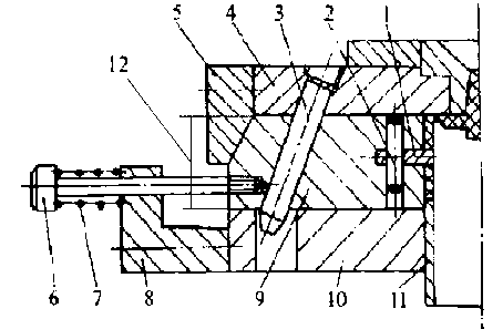
[0019] Such as figure 1 As shown, the present embodiment includes a fixed template 4 and a movable template 10. The fixed template 4 and the movable template 10 form a cavity, and the cavity is provided with a slider 9, an inclined guide post 3, a lateral core 1 and The ejector rod 11, the lateral core 1 is hinged with the slider 9, and the ejector rod 11 and the inclined guide post 3 are fixed in the cavity. The inclined guide column 3 is fixed on the fixed template 4, and the lateral core 1 is hinged with the slider 9 through the pin 2. When the mold is opened, the fixed template 4 moves up so that the inclined guide column 3 forces the slider 9 to slide on the movable template 10. Move to the left in the groove to complete the core-pulling action; in order to ensure that the inclined guide post 3 can accurately enter the inclined hole of the slider 9 when the mold is closed, so as to reset the slider 9, a positioning mechanism is provided on the mechanism, relying on the sc...

Embodiment 2

[0021] Such as figure 1 As shown, on the basis of Embodiment 1, this embodiment further includes a spring disposed at the bottom of the push rod 11, and the spring is a coil spring. The use of scroll springs can provide strong power for the rotation of the ejector rod 11, so that it can quickly complete the core-pulling action and improve the production efficiency of the injection mold; The rod 11 is subjected to an impact force, and the spring can buffer the impact force generated, thereby better protecting the equipment components and improving the service life of the equipment.

Embodiment 3

[0023] Such as figure 1 As shown, this embodiment is based on Embodiment 1. As a preference, the inclination angle of the inclined guide column 3 is 20°. If the inclination angle is too large, the space layout in the mold will be increased; if the inclination angle is too small, the slider 9 will move. The distance becomes smaller, and the effect of complete demoulding cannot be achieved. Therefore, the inclination angle is 20°, which not only satisfies a reasonable space layout, but also achieves a good demoulding effect;

[0024] Preferably, the core-pulling distance 12 is less than 80mm. If the core-pulling distance 12 is too long, the compression spring 7 or the length of the lateral core 1 will increase, thereby increasing the mold specification; if the core-pulling distance 12 is too short, the lateral core 1 cannot be completely pulled out from the plastic part. Limited to the internal structure layout of the injection molding machine, the core-pulling distance is lim...


PUM

PropertyMeasurementUnit
angleaaaaaaaaaa

Abstract

The invention declares a core-pulling and demoulding combination device, which comprises a fixed template and a movable template forming a cavity, wherein a slide block, an inclined guide post, a lateral mold core, a positioning mechanism and an ejector rod are arranged in the cavity; the lateral mold core is hinged to the slide block; the ejector rod and the inclined guide post are fixed in the cavity; the positioning mechanism comprises a compression spring and a bolt; the inclined guide post is fixed on the fixed template; the lateral mold core is hinged to the slide block through a pin; during mold opening, the fixed template move upwards, the inclined guide post drives the slide block to move to the left in a guide sliding chute in the movable template, so as to complete the core-pulling action; in order to guarantee that during mold closing, the inclined guide post can accurately enter into an inclined hole in the slide block to facilitate reset of the slide block, a positioning device is arranged on the mechanism; and with the bolt and the compression spring, the slide block is propped against a spacing stop block for positioning when withdrawn. During the whole process, the demoulding and core-pulling are good in processing property, the cost is low, and therefore, the device provided by the invention is suitable for medium and small sized injection moulded pieces.

Description

technical field [0001] The invention relates to the field of plastic molds, in particular to a core-pulling and demoulding combined device. Background technique [0002] Demolding is the last link in an injection molding cycle. Although the injection molded product is cold-set and formed, the demoulding still has a very important impact on the quality of the product. Improper demoulding methods may cause the product to be understressed during demoulding. Even, it will cause defects such as product deformation when ejected. [0003] After injection molding, the plastic part is cooled and shaped in the mold. When the plastic part has outer holes or inner and outer concaves, the plastic part cannot come out of the mold directly. Before the plastic part is ejected, the lateral core must be extracted, and then the plastic part is pushed out of the mold. Due to the shrinkage of the volume of the plastic part, a clamping force is generated on the lateral core. The core-pulling fo...

Claims


Application Information

Patent Timeline
Patent Type & Authority Applications(China)
IPC IPC(8): B29C45/33B29C45/40
Inventor 皮体斌陈忠桂
Owner AIMBON (CHENGDU) ELECTRIC APPLICANCE CO LTD
Why Eureka
Try Eureka