Hydraulic interconnection suspension system and exhausting and sealing method for same

A hydraulic interconnection suspension, hydraulic technology, applied in interconnection systems, fluid pressure actuation system components, suspensions, etc., can solve problems such as difficult air removal

Inactive Publication Date: 2015-04-15
苏州友邦汽车底盘科技有限公司
View PDF7 Cites 0 Cited by
  • Summary
  • Abstract
  • Description
  • Claims
  • Application Information

AI Technical Summary

Problems solved by technology

The air in the general hydraulic cylinder can only be discharged through the oil inlet and outlet, so it is not easy to discharge the air in the hydraulic cylinder

Method used


Image

  • Hydraulic interconnection suspension system and exhausting and sealing method for same

Examples


Embodiment Construction

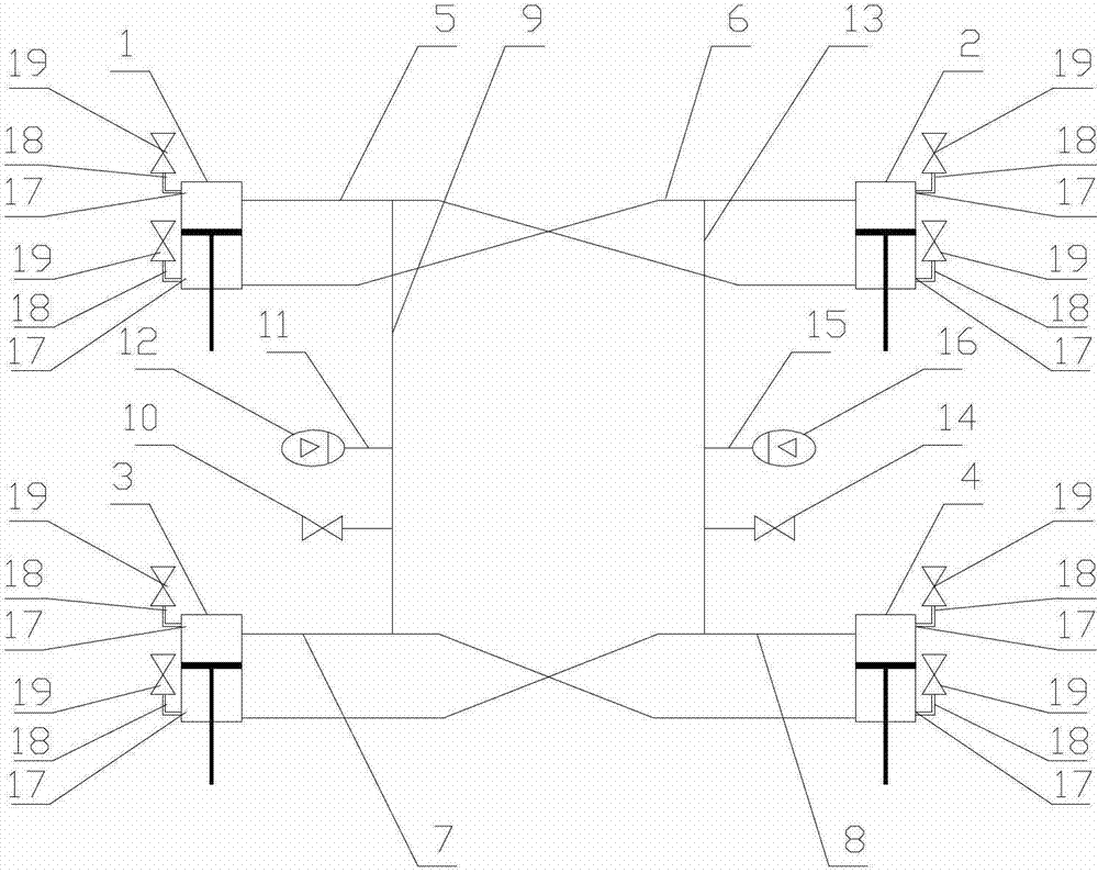
[0018] Specific embodiments of the present invention will be described in detail below in conjunction with the accompanying drawings.

[0019] like figure 1 As shown, a hydraulically interconnected suspension system includes first, second, third, and fourth hydraulic cylinders fixed between the vehicle frame and the axle, and the cavity on the side of the first hydraulic cylinder 1 away from the piston rod It communicates with the cavity near the piston rod side of the second hydraulic cylinder 2 through the first connecting pipe 5, and the cavity close to the piston rod side of the first hydraulic cylinder 1 and the cavity away from the piston rod side of the second hydraulic cylinder 2 pass through the second The connecting pipe 6 is connected; the cavity on the side away from the piston rod of the third hydraulic cylinder 3 communicates with the cavity on the side close to the piston rod of the fourth hydraulic cylinder 4 through the third connecting pipe 7, and the cavity ...


PUM


Abstract

The invention discloses a hydraulic interconnection suspension system. Four hydraulic cylinders, two energy storages, two spherical valves and hydraulic pipes are connected with one another to form two hydraulic branches of the hydraulic interconnection suspension system. The invention further provides an exhausting and sealing method for the hydraulic interconnection suspension system. The hydraulic interconnection suspension system and the exhausting and sealing method have the advantage that bubbles are prevented in the hydraulic branches when the hydraulic interconnection suspension system is used.

Description

technical field [0001] The invention relates to a hydraulic interconnection suspension system. Background technique [0002] The hydraulically interconnected suspension system is composed of two hydraulic branches connected by four hydraulic cylinders, two accumulators, two spherical valves and hydraulic pipes. The normal operation of the hydraulic interconnected suspension system requires that the two hydraulic branches reach the same working pressure and the system must not contain air bubbles. However, the air in the general hydraulic cylinder can only be discharged through the inlet and outlet ports, so it is not easy to discharge the air in the hydraulic cylinder. Contents of the invention [0003] The technical problem to be solved by the present invention is to provide a hydraulically interconnected suspension system in which air bubbles do not appear in the hydraulic branch circuit during use. [0004] In order to solve the above technical problems, the technical...

Claims


Application Information

Patent Timeline
Patent Type & Authority Patents(China)
IPC IPC(8): B60G21/06F15B21/04
Inventor 张农郑敏毅徐光中
Owner 苏州友邦汽车底盘科技有限公司
Why Eureka
Try Eureka