Through-flow submersible electric pump

A submersible electric pump, through-flow technology, applied in the direction of pumps, components of pumping devices for elastic fluids, pump devices, etc., can solve the problems of difficult maintenance and high manufacturing costs, and achieve reduced manufacturing accuracy, compact structure, and economical efficiency. The effect of manufacturing cost

Active Publication Date: 2013-09-04
HEFEI HENGDAJIANGHAI PUMP IND CO LTD
View PDF8 Cites 2 Cited by
  • Summary
  • Abstract
  • Description
  • Claims
  • Application Information

AI Technical Summary

Problems solved by technology

However, the planetary reduction gearbox is a precision component with high machining accuracy, high manufacturing cost and difficult maintenance

Method used


Image

  • Through-flow submersible electric pump
  • Through-flow submersible electric pump
  • Through-flow submersible electric pump

Examples


Embodiment Construction

[0021] The present invention will be further described through the embodiments below in conjunction with the accompanying drawings.

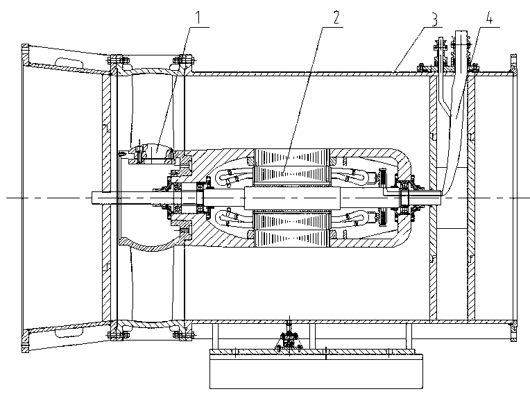
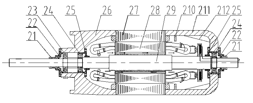
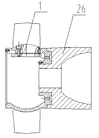
[0022] see figure 1 A through-flow submersible electric pump includes a cylindrical pump body 3 , an impeller 1 and a submersible motor 2 through which both ends pass through. see figure 2 , the motor includes a support shaft 29, the middle part of the support shaft 29 is covered with a stator 28, and the circumference of the yoke of the stator 28 is evenly distributed with ten ventilation holes 7 passing through the axial direction, see Figure 6 . The rotor 27 is sleeved on the stator 28, and the axial ends of the rotor 27 are respectively fixedly connected to the front end cover 26 and the rear end cover 211, and the protruding part of the middle part of the outer end surface of the front end cover 26 is used as the pump shaft, and is connected to one end of the wheel shaft of the impeller. See image 3 , The coupling is removed, which m...


PUM


Abstract

The invention relates to a through-flow submersible electric pump which comprises a cylindrical pump body, an impeller and a motor, wherein the two ends of the pump body are penetrated. The motor comprises a supporting shaft. The middle of the supporting shaft is sleeved by a stator. The stator is sleeved by a rotor, namely an outer rotor structure is adopted. The two axial ends of the rotor are fixedly connected with a front end cover and a rear end cover respectively. The portion between the front end cover and the supporting shaft and the portion between the rear end cover and the supporting shaft are respectively provided with a bearing through a bearing seat. The outer side end portion of the front end cover is connected with an impeller shaft of the impeller. The impeller shaft of the impeller is a hollow shaft and sleeved on the supporting shaft in a hollow mode. The two ends of the supporting shaft are respectively fixed in the pump body and coaxial to the pump body. The outer rotor structure is adopted, a motor shell of a traditional submersible motor and a gear reducer are removed, so that manufacturing accuracy is reduced; the gear reducer and the motor shell are not required, so that the structure is compact and a large amount of manufacturing cost is saved.

Description

technical field [0001] The invention belongs to the technical field of submersible electric pumps, and in particular relates to a through-flow submersible electric pump. Background technique [0002] Tubular flow submersible pumps are mostly installed horizontally and have the characteristics of straight and straight water flow. The operating conditions are generally large flow and low head. They are widely used in farmland irrigation, urban river drainage, flood fighting and emergency rescue, etc. With the advancement of science and technology and the needs of national infrastructure construction, tubular pumps are developing towards large-scale, low head, large flow, and large specific speed. At present, the direct connection between the low-speed inner rotor motor and the hydraulic components is mainly used, and the conventional submersible motor with a speed between 980-2980rpm is connected to the hydraulic components by using a planetary gear reducer. Tubular flow pump...

Claims


Application Information

Patent Timeline
Patent Type & Authority Applications(China)
IPC IPC(8): F04D13/08F04D29/10
Inventor 朱庆龙盛海军单丽鲍晓华金雷
Owner HEFEI HENGDAJIANGHAI PUMP IND CO LTD
Why Eureka
Try Eureka