
Tower mill

A tower mill and main motor technology, applied in grain processing, etc., can solve problems such as difficult installation and adjustment methods, difficult maintenance, strong randomness, etc., and achieve the effects of convenient addition of grinding media, convenient installation, and high mechanical efficiency

Active Publication Date: 2015-04-29
任茂福
View PDF5 Cites 7 Cited by
  • Summary
  • Abstract
  • Description
  • Claims
  • Application Information

AI Technical Summary

Problems solved by technology

[0002] The tower mill appeared in Japan in the 1950s. Compared with the horizontal ball mill, its size is slightly smaller, but its structure is more complicated, so it is more difficult to manufacture
The problems in its use are: the feeding process of the blades at the bottom of the spiral is highly random, and the probability of collision with the grinding medium is high, which is often accompanied by the jamming of the grinding medium, which not only causes a large amount of power consumption, but also consumes the grinding medium and The blades of the spiral agitator also make the blades at the bottom of the spiral agitator wear quickly; since the cylinder is closed, it is necessary to discharge the grinding media and materials in the cylinder during maintenance, and expose the internal parts of the cylinder as a whole, and sufficient maintenance space is required. It makes maintenance difficult; the tower mill is composed of several parts as a whole. In order to compensate the manufacturing and installation errors of the rotating parts, it is necessary to set up a coupling to compensate, so the overall size and weight of the equipment are increased, and the mechanical power consumption is also increased.
Since the connection parts of the main components of the tower mill are far away from the ground, it is also difficult to install and adjust this way.
In addition, when the machine is shut down with material, the grinding medium and material will settle and condense seriously, making it difficult to restart the equipment.
Therefore, the application range of this kind of tower mill is small, and it only occupies a small market range in the field of fine grinding, which is difficult for horizontal ball mills to handle.

Method used


Image

  • Tower mill
  • Tower mill
  • Tower mill

Examples


Embodiment

[0033] Example tower mill

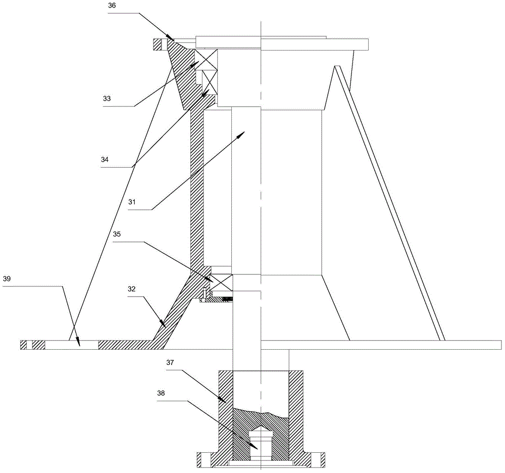
[0034] like Figure 1-Figure 8 Shown, a kind of tower mill is made up of main motor (10), reduction gear (20), support system (30), cylinder (40), door (50), helical agitator (60), protective liner ( 70) and slow start device (80) form.

[0035] The helical agitator (60) installed in the barrel (40) is composed of a screw shaft (61), a first helical blade group (62), a second helical blade group (63) and double-headed material taking blades (64). At the bottom of the spiral agitator (60), the bottom end of the first helical blade group (62) and the bottom end of the second helical blade group (63) form a double-headed helix symmetrical structure and are connected with the double-headed feeding blades (64). The head takes material blade (64) and fixes with the threaded surface of bolt and screw shaft (61) by the installation area (64-1) on the installation surface.

[0036] The double-head reclaiming blade (64) blade is helical, and its helical su...


PUM


Abstract

The invention discloses a tower mill. A technical scheme adopted by the tower mill is that the tower mill comprises a main motor, a speed reducing device, a supporting system, a cylinder, a door, a spiral stirrer and protective lining plates, wherein the main motor is connected with the speed reducing device, the speed reducing device is arranged on the supporting system, the supporting system is a completely-closed structure, a driving shaft is arranged in the supporting system, the upper end of the driving shaft is connected with the speed reducing device, and the lower end of the driving shaft is connected with a screw rod shaft of the spiral stirrer by virtue of a shaft sleeve; the protective lining plates are arranged on the inner walls of the cylinder and the door; the bottom end of a first spiral blade group and the bottom end of a second spiral blade group are connected with a double-head material picking blade which is fixedly arranged on the screw rod shaft; a discharge opening and a feed opening are formed in the cylinder; and the door is movably connected with the cylinder. By adopting the tower mill disclosed by the invention, the grinding efficiency of the tower mill can be significantly improved, the service life of wear-out parts can be prolonged, the loss of a grinding medium can be reduced, the assembly and use of the tower mill can be facilitated, the mechanical efficiency of the tower mill can be improved, and the manufacturing cost of the tower mill can be reduced.

Description

technical field [0001] The invention relates to a tower mill with a new structure used for grinding various materials in ore dressing and other industries. Background technique [0002] The tower mill appeared in Japan in the 1950s. Compared with the horizontal ball mill, its size is slightly smaller, but its structure is more complicated, so it is more difficult to manufacture. The problems in its use are: the feeding process of the blades at the bottom of the spiral is highly random, and the probability of collision with the grinding medium is high, which is often accompanied by the jamming of the grinding medium, which not only causes a large amount of power consumption, but also consumes the grinding medium and The blades of the spiral agitator also make the blades at the bottom of the spiral agitator wear quickly; since the cylinder is closed, it is necessary to discharge the grinding media and materials in the cylinder during maintenance, and expose the internal parts ...

Claims


Application Information

Patent Timeline
Patent Type & Authority Applications(China)
IPC IPC(8): B02C17/10B02C17/16B02C17/18B02C17/24
CPCB02C17/10B02C17/16B02C17/163B02C17/18B02C17/1825B02C17/24
Inventor 任茂福
Owner 任茂福
Learn More