A thin induction cooker

An induction cooker, thin technology, applied in household stoves/stoves, electric heating fuel, household heating, etc., can solve the problems of being sucked into the inside of the induction cooker and affecting the life of the electric components of the induction cooker, and achieve the effect of reducing moisture and prolonging the service life

Active Publication Date: 2016-04-20
JOYOUNG CO LTD
View PDF10 Cites 0 Cited by
  • Summary
  • Abstract
  • Description
  • Claims
  • Application Information

AI Technical Summary

Problems solved by technology

[0003] In the process of realizing and using the above-mentioned induction cooker, the inventor found that there are at least the following problems in the prior art: since the air inlet of the fan is directly arranged on the bottom wall of the base, and the bottom wall of the base is generally placed on the cooking table, such as a stove Tables, tables, etc., when the fan sucks the external cooling air from the air inlet, it is easy to suck the moisture on the stove and table into the inside of the induction cooker, which will affect the life of the electrical components inside the induction cooker; especially the bottom wall of the base When the scheme of setting the air inlet on the top is applied to the ultra-thin induction cooker, since the bottom wall is closer to the cooking surface, it is easier for the fan to absorb the moisture on the cooking surface

Method used


Image

  • A thin induction cooker
  • A thin induction cooker
  • A thin induction cooker

Examples


Embodiment Construction

[0030] The following will clearly and completely describe the technical solutions in the embodiments of the present invention with reference to the accompanying drawings in the embodiments of the present invention. Obviously, the described embodiments are only some, not all, embodiments of the present invention. Based on the embodiments of the present invention, all other embodiments obtained by persons of ordinary skill in the art without creative efforts fall within the protection scope of the present invention.

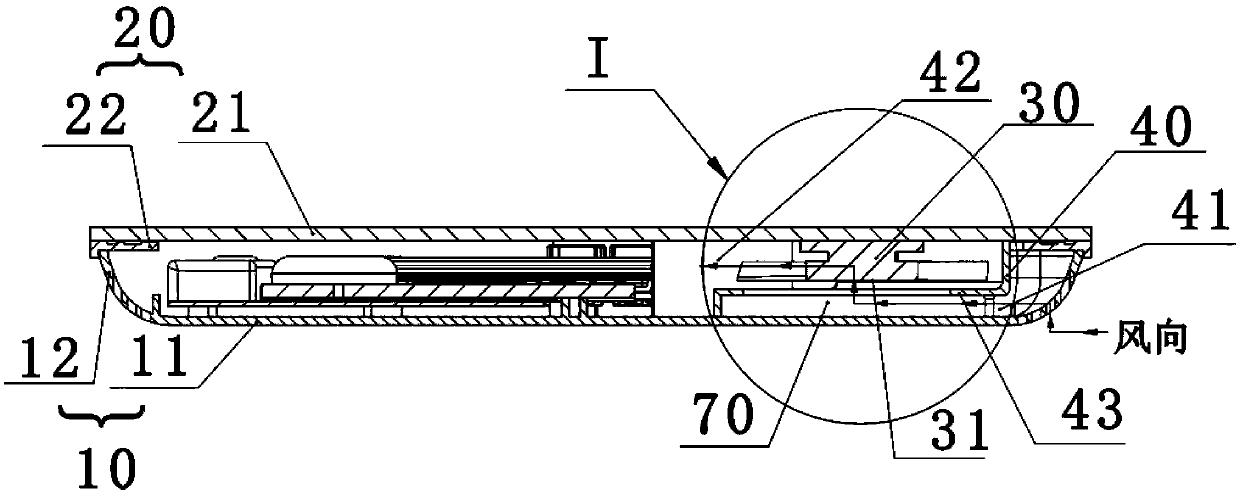
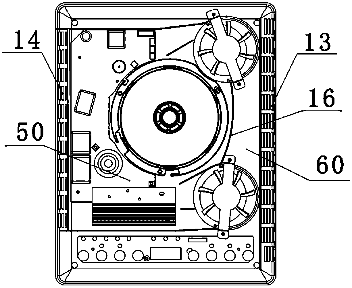
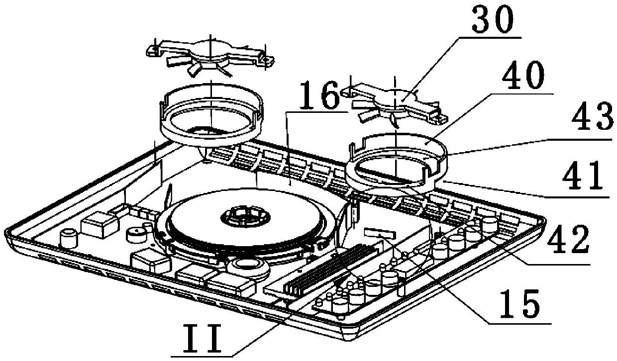
[0031] An embodiment of the present invention provides a thin induction cooker, such as figure 1 As shown, the induction cooker includes a base 10 and an upper cover assembly 20 forming a furnace cavity. A fan 30 is placed horizontally in the cavity. The horizontal position here mainly means that the axial end surface of the fan 30 is arranged parallel to the bottom wall of the base 10 . Such as figure 2 As shown, an air guide cover 40 is arranged on the peripher...


PUM


Abstract

The embodiment of the invention discloses a thin-type induction cooker, which relates to the technical field of kitchen cooking and solves the problem that moisture is easily inhaled when wind enters the bottom of a conventional induction cooker. The thin-type induction cooker comprises a pedestal and an upper cover assembly which form a cooker cavity, wherein a fan lays in the cooker cavity, a wind scooper is arranged at the periphery of the fan, a heating cavity and a cold wind cavity are formed at two sides of the wind scooper respectively, heating elements are arranged in the heating cavity, and lateral air inlets, through which cooling wind enters the cold wind cavity, are formed in the side wall of the cold wind cavity; and a fan wind inlet is formed in the bottom of one side, facing the cold wind cavity, of the wind scooper, a fan wind outlet is formed in one side, facing the heating elements, of the wind scooper, a wind inlet gap is formed between the bottom surface of the fan and the bottom wall of the pedestal, and the cooling wind in the cold wind cavity enters the wind inlet gap through the fan wind inlet, is inhaled by the fan and is blown towards the heating elements through the fan wind outlet. The technical scheme provided by the embodiment of the invention is mainly applied to induction cookers and is particularly suitable for ultrathin induction cookers with relatively high heat dissipation requirements.

Description

technical field [0001] The invention relates to the technical field of kitchen cooking, in particular to a thin electromagnetic cooker. Background technique [0002] The induction cooker mainly uses the alternating magnetic field generated by the electromagnetic coil for heating. In order to generate the alternating magnetic field, it is necessary to pass high-frequency alternating current into the electromagnetic coil, so switching elements such as IGBT are required to control the current flowing into the electromagnetic coil. . As a result, the original components such as IGBT and electromagnetic coil will generate high heat, so it is necessary to design a corresponding heat dissipation structure on the induction cooker. Chinese patent 201120502183.9 discloses a heat dissipation structure of an induction cooker. In this heat dissipation structure, a fan is installed on the base, and air inlets are arranged on the bottom wall and the side wall of the base. The main air inl...

Claims


Application Information

Patent Timeline
Patent Type & Authority Patents(China)
IPC IPC(8): F24C7/00F24C15/00
Inventor 朱泽春陈宁涛高朝岗胡文飞
Owner JOYOUNG CO LTD
Why Eureka
Try Eureka