
Roof-cutting pressure relief method in hard-roof deep-hole pre-splitting blasting

A technology of pre-splitting blasting and top-cutting pressure relief, which is applied in the field of blasting pressure relief, can solve the problems of coal pillar stress concentration and strong mine pressure along the goaf roadway, reduce the deformation and damage of the roadway, and improve the stability of the coal pillar , the effect of wide practicability

Inactive Publication Date: 2015-02-25
LIAONING TECHNICAL UNIVERSITY
View PDF3 Cites 2 Cited by
  • Summary
  • Abstract
  • Description
  • Claims
  • Application Information

AI Technical Summary

Problems solved by technology

[0003] Aiming at the problems existing in the prior art, the present invention provides a roof cutting and pressure relief method for deep hole pre-splitting blasting on a hard roof, which solves the problems of coal pillar stress concentration and It has obvious effect and wide practicability for problems such as strong mine pressure in gob-side roadway

Method used


Image

  • Roof-cutting pressure relief method in hard-roof deep-hole pre-splitting blasting
  • Roof-cutting pressure relief method in hard-roof deep-hole pre-splitting blasting
  • Roof-cutting pressure relief method in hard-roof deep-hole pre-splitting blasting

Examples


Embodiment 1

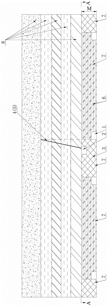
[0029] like Figure 1 to Figure 3 As shown, the thickness M of the coal seam in this embodiment is 10m, which specifically includes the following steps:

[0030] Step 1: Arrange the roof cutting roadway 2

[0031] The coal seam 7 is a very thick coal seam 7, so before the mining of the working face 6, the roof cutting roadway 2 is excavated along the roof of the coal seam 7 in the coal pillar 3, and the horizontal offset distance S between the roof cutting roadway and the mining roadway is 7m ;

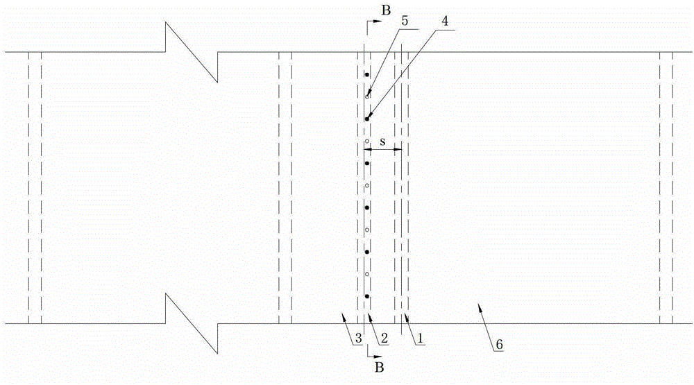
[0032] Step 2: Arrange blast hole 4 and control hole 5

[0033] The inclined blasting hole 4 and the control hole 5 are longitudinally arranged in the roof rock layer 8 above the entire roof cutting roadway 2, and the control hole 5 is arranged in the middle position between the adjacent blasting holes 4; The distance of the roadway of the roof cutting roadway 2 close to the working face 6 is 1.5m, the bottom of the hole is set in the vertical plane of the roadway of the mining roa...

Embodiment 2

[0037] like Figure 4 to Figure 5 As shown, the thickness M of the coal seam in this embodiment is 5m, which specifically includes the following steps:

[0038] Step 1: Arrange the roof cutting roadway 2

[0039] The coal seam 7 is a thick coal seam 7, and the mining roadway 1 is used as the roof cutting roadway 2;

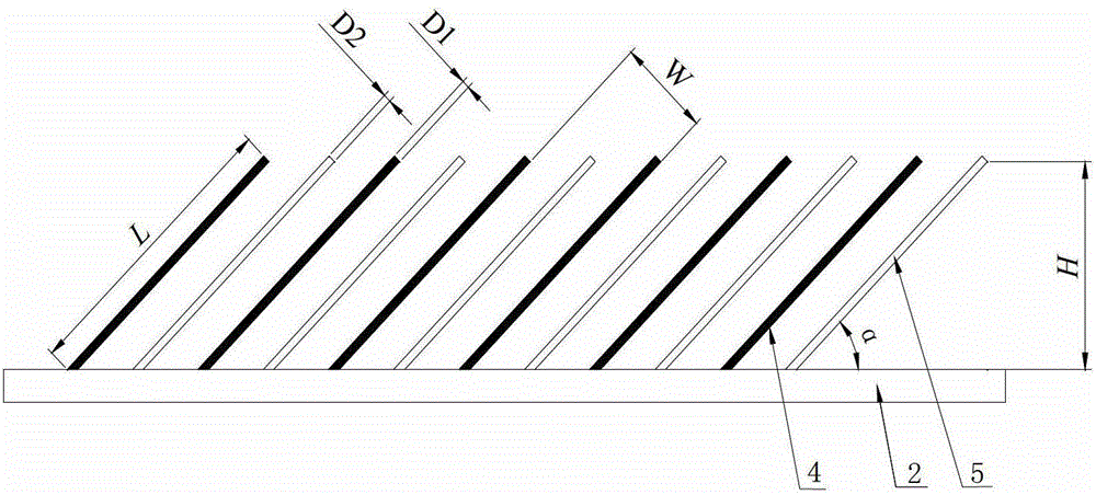
[0040] Step 2: Arrange blast hole 4 and control hole 5

[0041] The coal seam 7 and the roof rock layer 8 above the entire roof cutting roadway 2 are longitudinally provided with inclined blasting holes 4 and control holes 5, and the control holes 5 are arranged in the middle position between adjacent blasting holes 4; blasting holes 4 and control holes The distance between 5 and the roof cutting roadway 2 near the coal pillar 3 is 1.5m, the blasting hole 4 and the control hole 5 are arranged in parallel in the same vertical plane, and the included angle α between the blasting hole (control hole) and the coal seam roof is 45° , the distance W between adjacent b...


PUM


Abstract

The invention relates to a roof-cutting pressure relief method in hard-roof deep-hole pre-splitting blasting, belongs to the technical field of blasting pressure relief, relates to a method of controlling coal pillar stress concentration and intense gob-side entry strata behaviors caused by suspension of gob hard roofs in thick seams and super high seams, and solves such problems of coal pillar stress concentration and intense gob-side entry strata behaviors caused by suspension of gob hard roofs in thick seams and super high seams. The method is effective and widely applicable and includes the steps of firstly, reserving a roof-cutting roadway in coal pillars along a seam roof before working face extraction in case of the seam being the super high seam; if the seam is the thick seam, directly using a mining roadway as a roof-cutting roadway; secondly, if the seam is the super high seam, longitudinally reserving blast holes in the roof strata above the roof-cutting roadway; and thirdly, loading explosives, sealing the holes and allowing for roof-cutting blasting.

Description

technical field [0001] The invention belongs to the technical field of blasting and pressure relief, and relates to a method for preventing and controlling the stress concentration of coal pillars caused by the overhanging roof of a hard roof in a goaf of thick coal seams and extra-thick coal seams and the appearance of strong mining pressure in gobs, in particular to a hard roof. Deep hole pre-split blasting top cutting pressure relief method. Background technique [0002] In the mining of thick coal seams and extra-thick coal seams, especially when the roof is a multi-layered hard rock layer with a large thickness, as the working face advances forward, a cantilever beam of a certain length is formed with the coal pillar as the supporting point. Overburden. With the periodic pressure of the working face, the roof of this layer is inclined to the goaf at a certain angle, the falling gangue is difficult to fill the goaf, the lateral concentrated stress increases, the coal bo...

Claims


Application Information

Patent Timeline
Patent Type & Authority Patents(China)
IPC IPC(8): F42D3/00
Inventor 张宏伟朱志洁陈蓥霍丙杰兰天伟
Owner LIAONING TECHNICAL UNIVERSITY
Learn More