Clutch friction plate flatness testing equipment and using method thereof
What is Al technical title?
Al technical title is built by PatSnap Al team. It summarizes the technical point description of the patent document.
A test equipment and friction plate technology, applied in the field of clutch friction plate flatness test equipment, can solve the problems of time-consuming replacement of fixtures, time-consuming test piece installation, low degree of automation, etc., to achieve fast and simple installation, fast tool replacement, and automation. high effect
Inactive Publication Date: 2013-09-04
HANGZHOU DIANZI UNIV
View PDF4 Cites 9 Cited by
Summary
Abstract
Description
Claims
Application Information
AI Technical Summary
This helps you quickly interpret patents by identifying the three key elements:
Problems solved by technology
Method used
Benefits of technology
Problems solved by technology
At present, the clutch friction plate flatness test equipment generally has the disadvantages of low degree of automation, time-consuming installation of test pieces, time-consuming replacement of tooling and fixtures, and low test accuracy. The clutch friction plate flatness test equipment, process and method with higher precision have become a hot spot and a new direction in the clutch friction plate industry
Method used
Image
Click on the blue label to locate the original text in one second.
Reading with bidirectional positioning of images and text.
Examples
Embodiment Construction
[0035] The present invention will be further described below in conjunction with accompanying drawing.
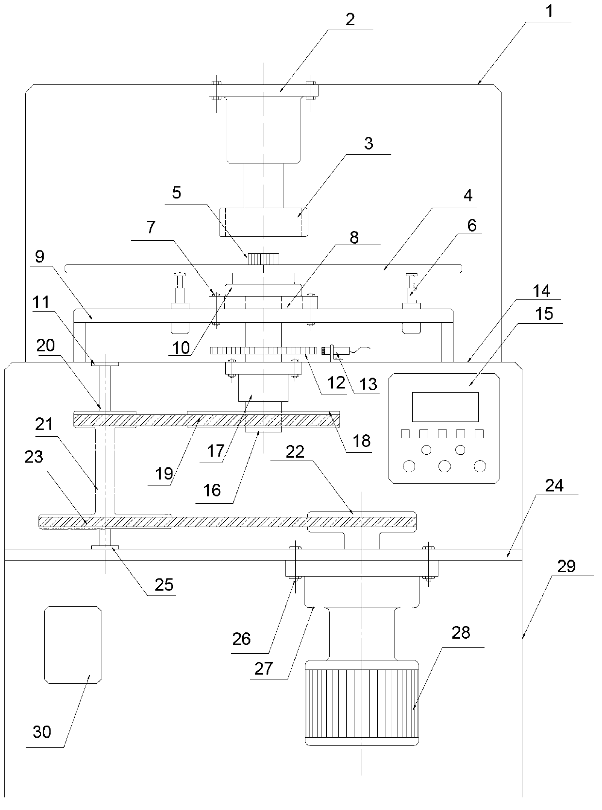
[0036]A device for testing the flatness of a clutch friction plate, comprising an upper structure and a lower structure.
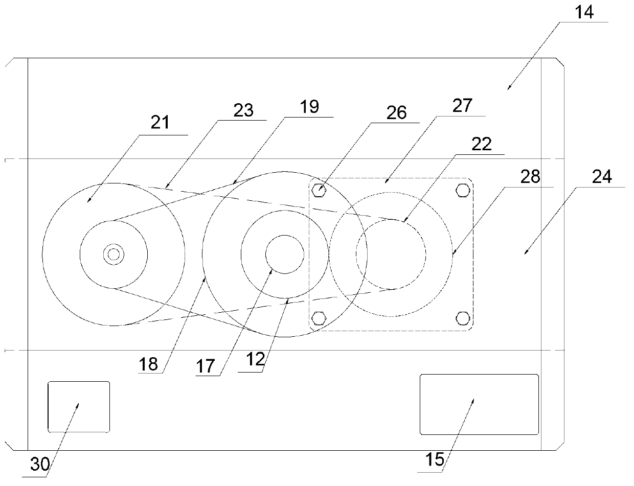
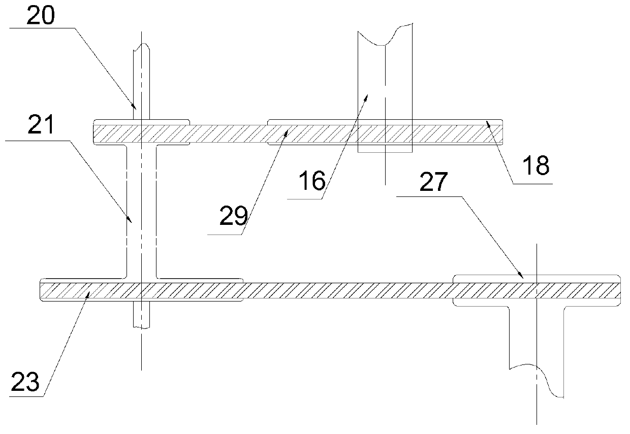
[0037] Such as figure 1 As shown, the upper structure includes a cylinder bracket 1, a cylinder 2, a linear bearing 3, a tested friction plate 4, a spline seat 5, a precision sensor bracket 9, a gear plate 12, a magnetoelectric sensor 13, and an operating table 14; The cylinder bracket 1 is provided with a cylinder 2, and the cylinder 2 is fixed on the lower surface of the top of the cylinder bracket by bolts, the linear shaft 3 is arranged under the cylinder 2, the tested friction plate 4 is set under the linear bearing 3, and the tested friction plate 4 is set on the flower. On the key base 5, the lower end of the spline base 5 is provided with a main shaft connecting flange 10, and the lower end of the main shaft connecting flange 10 is provided wit...
PUM
Abstract
The invention discloses clutch friction plate flatness testing equipment and a using method thereof. The clutch friction plate flatness testing equipment comprises an upper structure and a lower structure. The upper structure comprises an air cylinder support, an air cylinder, a linear bearing, a tested friction plate, a spline seat, a precise sensor support, a fluted disc, a magnetoelectric sensor and an operating console. The lower structure comprises a belt pulley upper end bearing, a control box, a main shaft, a main bearing, a belt pulley III, a triangular belt II, a belt pulley shaft, a belt pulley II, a belt pulley I, a triangular belt I, a motor supporting plate, a belt pulley lower end bearing, motor fixing bolts, a gearbox, an alternating-current motor, a lower support and a frequency converter. A main transmission system, a friction plate bearing mechanism and a precise probe fixture are arranged in the upper structure and the lower structure. The clutch friction plate flatness testing equipment has the characteristics of higher rapidness and simplicity in installation, high automation level, convenience in testing operation and the like, and can better guarantee the accuracy of clutch friction plate flatness testing.
Description
technical field [0001] The invention belongs to the technical field of continuous measuring equipment, and in particular relates to a clutch friction plate flatness testing equipment and a using method thereof. Background technique [0002] The clutch is an important part to ensure the car starts smoothly, shifts gears smoothly, and handles lightly. For the friction clutch, the performance of the friction plate directly affects the service life of the clutch, the stability of the vehicle transmission system and the safety of the vehicle. Therefore, flatness testing equipment is a production license product that is related to the safety of people's lives and property. At present, domestic and foreign countries have paid more and more attention to the research on the performance of clutch friction plates, especially in the smoothness of friction plates. At present, the clutch friction plate flatness test equipment generally has the disadvantages of low degree of automation, ...
Claims
Application Information
Patent Timeline
Application Date:The date an application was filed.
Publication Date:The date a patent or application was officially published.
First Publication Date:The earliest publication date of a patent with the same application number.
Issue Date:Publication date of the patent grant document.
PCT Entry Date:The Entry date of PCT National Phase.
Estimated Expiry Date:The statutory expiry date of a patent right according to the Patent Law, and it is the longest term of protection that the patent right can achieve without the termination of the patent right due to other reasons(Term extension factor has been taken into account ).
Invalid Date:Actual expiry date is based on effective date or publication date of legal transaction data of invalid patent.