
Fiber Bragg Grating Seismic Acceleration Detector Based on Combined Cantilever Beam Structure

A seismic acceleration and fiber grating technology, applied in the direction of seismic signal receivers, etc., can solve the problems of large dynamic range and can not meet the sensitivity at the same time, and achieve the effect of large dynamic range, high sensitivity and wide response frequency.

Inactive Publication Date: 2015-10-14
NORTHWEST UNIV
View PDF3 Cites 0 Cited by
  • Summary
  • Abstract
  • Description
  • Claims
  • Application Information

AI Technical Summary

Problems solved by technology

[0005] It overcomes the shortcomings of existing acceleration detectors that cannot simultaneously meet technical indicators such as high sensitivity, wide response frequency bandwidth, large dynamic range, and simple production.

Method used


Image

  • Fiber Bragg Grating Seismic Acceleration Detector Based on Combined Cantilever Beam Structure
  • Fiber Bragg Grating Seismic Acceleration Detector Based on Combined Cantilever Beam Structure
  • Fiber Bragg Grating Seismic Acceleration Detector Based on Combined Cantilever Beam Structure

Examples


Embodiment Construction

[0012] Below in conjunction with accompanying drawing, content of the invention will be further described:

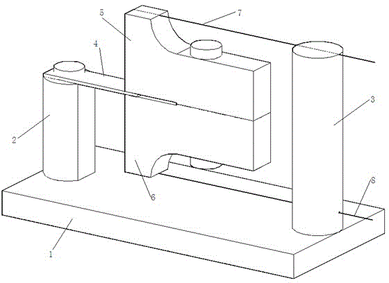
[0013] refer to figure 1 As shown, the fiber grating seismic acceleration detector based on the combined cantilever beam structure includes a plate base 1, and the top of the base 1 is provided with a columnar support column 2 and a columnar connector 3, and the connector 3 is processed with a through hole. The top of the column 2 is fixed to one end of the cantilever beam 4 with the same cross-section, and the other end of the cantilever beam 4 with the same cross-section is connected to the mass block. The L-shaped cantilever beam 5 and the second right-angle folding ruler L-shaped cantilever beam 6 are combined. An outer wall of the ruler L-shaped cantilever beam 6 is overlapped and combined in a mirror image from top to bottom, the upper end of the mass block and the upper end of the connecting piece 3 are on the same level, and the lower end of the mass block is ...


PUM


Abstract

A fiber grating earthquake acceleration detector based on a combined type cantilever structure comprises a board-shaped base. A cylindrical supporting column and a cylindrical connecting piece are arranged at the top of the base. A through hole is formed in the connecting piece. The supporting column is fixed with one end of a uniform-section cantilever. The other end of the uniform-section cantilever is connected with a mass block. The mass block is uniform in shape and size and is formed by combination of a first right-angle folding ruler L-type cantilever and a second right-angle folding ruler L-type cantilever which are of a right-angle folding ruler L type. A first fiber grating and a second fiber grating which are made of the same material and identical in length are further arranged between the mass block and the connecting piece. The first fiber grating and the second fiber grating are in series connection in a fused mode outside the connecting piece. According to the fiber grating earthquake acceleration detector based on the combined type cantilever structure, the shortages that an existing acceleration detector can not satisfy the technical indexes of high flexibility, wide response bandwidth, a large dynamic range, simple manufacturing and the like are overcome.

Description

technical field [0001] The invention belongs to the technical field of optical fiber seismic acceleration detector devices, and in particular relates to an optical fiber grating seismic acceleration detector based on a combined cantilever beam structure. Background technique [0002] At present, borehole seismic exploration technology, as a new technology in the field of oil and gas field exploration and development, has been paid more and more attention by people. The resulting borehole exploration method based on optical fiber technology is a new technology that has emerged in recent years. One of the most promising development directions. Among them, fiber Bragg grating has the advantages of anti-electromagnetic interference, easy cascading, and simple wavelength demodulation, so it is an important aspect of seismic technology research to use fiber Bragg grating as a sensing element for seismic detection. [0003] The existing fiber grating acceleration detectors have va...

Claims


Application Information

Patent Timeline
Patent Type & Authority Patents(China)
IPC IPC(8): G01V1/18
Inventor 乔学光冯定一荣强周杜彦英忽满利冯忠耀
Owner NORTHWEST UNIV
Learn More