Slit grating array component used for switching 2D/3D displaying modes

A slit grating and array component technology, applied in the field of slit grating array components, can solve the problems of increased cost, large electric field spacing, long conversion response time, etc., and achieves the effects of excellent switching effect, low implementation difficulty and low cost.

Active Publication Date: 2013-09-04
FUZHOU UNIV
View PDF11 Cites 4 Cited by
  • Summary
  • Abstract
  • Description
  • Claims
  • Application Information

AI Technical Summary

Problems solved by technology

In US6069650 and CN1892289, the researchers used the different refractive indices of liquid crystals for o-light and e-light to realize 2D / 3D conversion. They all need to plate a conductive thin layer or a conductive layer with a gradient structure on the surface of the microlens array to achieve control of the liquid crystal. However, this method has very high requirements on the process, and it is difficult to guarantee the processing accuracy of the coating film, and the large electric field distance leads to a long switching response time, which will lead to unsatisfactory display functions and effects.
In US6157424, the inventor replaced the traditional slit grating assembly with a striped liquid crystal panel barrier, and used the switching liquid crystal panel to achieve the purpose of 2D / 3D switching, but the main disadvantage of this method is that the added striped liquid crystal panel is relatively expensive , so the cost of manufacturing the entire 2D / 3D switching device also increases, and the switching of liquid crystals cannot completely replace the light shielding effect of the grating, and the display effect of 2D / 3D switching is not ideal
In short, the existing 2D / 3D switching devices need to be improved in terms of technology, cost, and practicability

Method used


Image

  • Slit grating array component used for switching 2D/3D displaying modes
  • Slit grating array component used for switching 2D/3D displaying modes
  • Slit grating array component used for switching 2D/3D displaying modes

Examples


Embodiment Construction

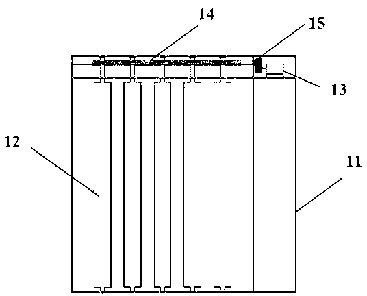
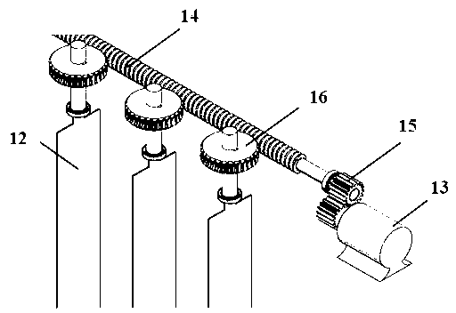
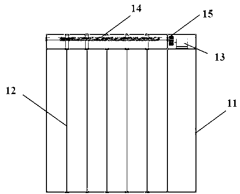
[0026] The present invention provides preferred embodiments, which are only used for further description of the present invention, and should not be considered as being limited to the embodiments set forth herein, nor can they be interpreted as limiting the protection scope of the present invention. Some non-essential improvements and adjustments made to the present invention still belong to the protection scope of the present invention. In the figure, mechanisms such as light blocking strips, motors, bearings, worm gears, and baffles are idealized models, and should not be regarded as strictly stipulating their parameters and geometric dimensions. Here, the referenced figures are schematic diagrams of idealized embodiments of the present invention, and the illustrated embodiments of the present invention should not be considered limited to the specific shapes of regions shown in the figures, but include other shapes capable of performing the same function. The accessories in ...


PUM


Abstract

The invention relates to a slit grating array component used for switching 2D / 3D displaying modes. The slit grating array component used for switching the 2D / 3D displaying modes is characterized by comprising a frame, a plurality of light-shielding bars are evenly arranged inside the frame at intervals, a worm gear is arranged at the upper end portion of each light-shielding bar, all worm gears are meshed with a worm, the worm is meshed with a rotary shaft gear of a stepping motor through a gear to drive the worm gears to rotate, and 90-degree rotation of each light-shielding bar is achieved. The slit grating array component used for switching the 2D / 3D displaying modes can achieve switching of 2D / 3D images of a whole screen in real time. Compared with other flat displaying devices capable of switching 2D / 3D, the slit grating array component used for switching the 2D / 3D displaying modes has the advantages of being low in implementation difficulty, fast in response, good in switching effect, simple in structure, high in reliability, low in cost, and capable of achieving the low-cost high-quality 2D / 3D switching effect.

Description

technical field [0001] The invention relates to the field of stereoscopic display, in particular to a slit grating array assembly for switching between 2D / 3D display modes. Background technique [0002] The autostereoscopic display device realizes the recognition of stereoscopic images through the principle of parallax. Since there is a subtle difference in the depth of objects observed by the left and right eyes of the human being, the stereoscopic images can finally be perceived. Stereoscopic display technology uses artificial means to create the parallax of the left and right eyes of people, so that the left and right eyes can observe two images with parallax respectively, and then through the fusion of the images by the brain, it can produce the effect of observing real three-dimensional objects without the need with any other equipment. In the current research results, there are two widely used stereoscopic display devices: slit grating type stereoscopic display device...

Claims


Application Information

Patent Timeline
Patent Type & Authority Applications(China)
IPC IPC(8): G02B27/22H04N13/04
Inventor 陈恩果张永爱郭太良周雄图胡利勤叶芸林锑杭
Owner FUZHOU UNIV
Why Eureka
Try Eureka