Laminating device and laminating method for iron cores of reactors

A reactor and iron core technology, which is applied in the manufacture of inductors/transformers/magnets, circuits, electrical components, etc., can solve the problem of insufficient flatness of the processed iron core, inconsistencies in the size of the iron core column, the plane, and large air gap errors, etc. problem, to achieve the effect of improving flatness, reducing air gap error and improving production efficiency

Active Publication Date: 2013-09-04
襄阳中车电机技术有限公司
View PDF7 Cites 19 Cited by
  • Summary
  • Abstract
  • Description
  • Claims
  • Application Information

AI Technical Summary

Problems solved by technology

[0005] The technical problem to be solved by the present invention is to overcome the deficiencies of the prior art, and to provide a stacking device for reactor iron cores, which can effectively solve the inconsistency of the process

Method used


Image

  • Laminating device and laminating method for iron cores of reactors
  • Laminating device and laminating method for iron cores of reactors
  • Laminating device and laminating method for iron cores of reactors

Examples


Embodiment 1

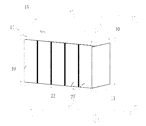
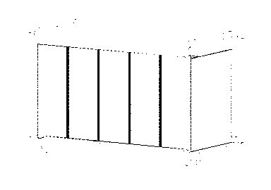
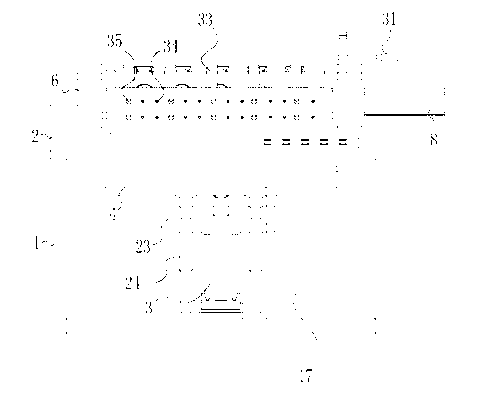
[0035] Embodiment 1: as Figure 3 to Figure 5 As shown, a lamination device for reactor cores includes a frame 1, a panel 2 arranged on the upper part of the frame 1, and a lower cylinder 3 arranged on the lower part of the frame 1, which is arranged on The flat plate 4 parallel to the panel 2 on the output shaft of the lower cylinder 3, the lamination frame 5 and the brackets 6 that are located on both sides and are rotatably connected to it, and are arranged on the lamination frame 5 for The vertical pressurized vertical cylinder 7 and the horizontal cylinder 8 arranged on the support 6, the output shaft of the horizontal cylinder 8 passes through the support 6 and the lamination frame side 27 from the lateral pressurization, and is arranged on The upper gusset splint 10 and the lower gusset splint 11 are used to clamp the iron core 9 to be processed in the lamination frame 5, and the panel 2 has a cavity 12 whose size matches the size of the flat plate 4. The flat plate 4 ...

Embodiment 2

[0052] Embodiment 2: Compared with Embodiment 1, the difference is only that: the acute angle slope 18 between the panel and the horizontal line is set to 7 degrees, and the bolts 31 are respectively inserted into the two bolt positioning holes 29 and the side positioning The lamination frame 5 is respectively fixed in the hole 30 at the position where the cross section of the lamination frame is perpendicular to the horizontal line and at the position where the cross section of the lamination frame and the cross section of the panel form an obtuse angle 36 of 100 degrees.

Embodiment 3

[0053] Embodiment 3: Compared with Embodiment 1, the difference is only that: the acute angle slope 18 between the panel and the horizontal line is set to 8 degrees, and the bolts 31 are respectively inserted into the two bolt positioning holes 29 and the side positioning The lamination frame 5 is fixed in the hole 30 at the position where the cross section of the lamination frame is perpendicular to the horizontal line and at the position where the cross section of the lamination frame and the cross section of the panel form an obtuse angle 36 of 110 degrees.

[0054]To sum up, the present invention adopts the electro-pneumatic principle, uses the vertical cylinder, the horizontal cylinder and the bottom cylinder to pressurize the processed iron core from three directions, so that the pressing force of each column of the processed iron core is consistent, Thereby ensuring the consistency of its size and plane, reducing the air gap error between the processed iron core columns,...


PUM


Abstract

The invention discloses a laminating device for iron cores of reactors. The laminating device comprises a framework, a panel, a lower cylinder, a flat plate, a laminating frame, supports, vertical cylinders, a transverse cylinder, an upper-end angle bracing clamp plate and a lower-end angle bracing clamp plate. The flat plate is arranged on an output shaft of the lower cylinder and is parallel to the panel, the supports are positioned on two sides of the laminating frame and are rotationally connected with the laminating frame, the vertical cylinders are arranged on the laminating frame, and the transverse cylinder is arranged on the supports. The invention further discloses a laminating method implemented by the aid of the laminating device. The laminating device and the laminating method have the advantages that a machined iron core is pressed by the vertical cylinders, the transverse cylinder and the bottom cylinder from three directions according to an electro-pneumatic principle, pressing force applied to each core column of the machined iron core is consistent, accordingly, the dimensional consistency and the plane consistency of the machined iron core are guaranteed, errors due to air gaps among the core columns of the machined iron core are reduced, and the integral flatness of the machined iron core and the production efficiency are improved.

Description

technical field [0001] The invention relates to a device for stacking iron cores of reactors and a stacking method thereof, belonging to the field of electrical parts processing tooling. Background technique [0002] In the process of producing reactor cores, the silicon steel sheets are usually clamped and laminated with simple channel steel, and then glued and baked to fix the core column into a whole. Tighten the coil with stays in the assembled iron core. In the production process, there are often phenomena such as the size and plane of the processed iron core columns are inconsistent, the flatness is not high enough, and the error of the air gap between the processed iron core columns is large, which makes the product structurally stable. Not strong, poor shock and vibration resistance, high noise and other phenomena, and affect the later assembly, resulting in long production cycle and low production efficiency. [0003] The Chinese utility model patent with the publ...

Claims


Application Information

Patent Timeline
IPC IPC(8): H01F41/02
Inventor 沈陈兵盛政彬鲁力张木生
Owner 襄阳中车电机技术有限公司
Why Eureka
Try Eureka