Optical module and electric domain dispersion compensation method thereof

A dispersion compensation, optical module technology, applied in the direction of eliminating distortion/dispersion, optical fiber transmission, transmission monitoring/testing/fault measurement system, etc., can solve the problem of poor electrical signal compensation, electrical signal delay and distortion, electrical signal loss and other problems, to achieve better dispersion compensation, reduce delay and distortion, and reduce maintenance costs.

Inactive Publication Date: 2013-09-04
HISENSE BROADBAND MULTIMEDIA TECH
View PDF6 Cites 12 Cited by
  • Summary
  • Abstract
  • Description
  • Claims
  • Application Information

AI Technical Summary

Problems solved by technology

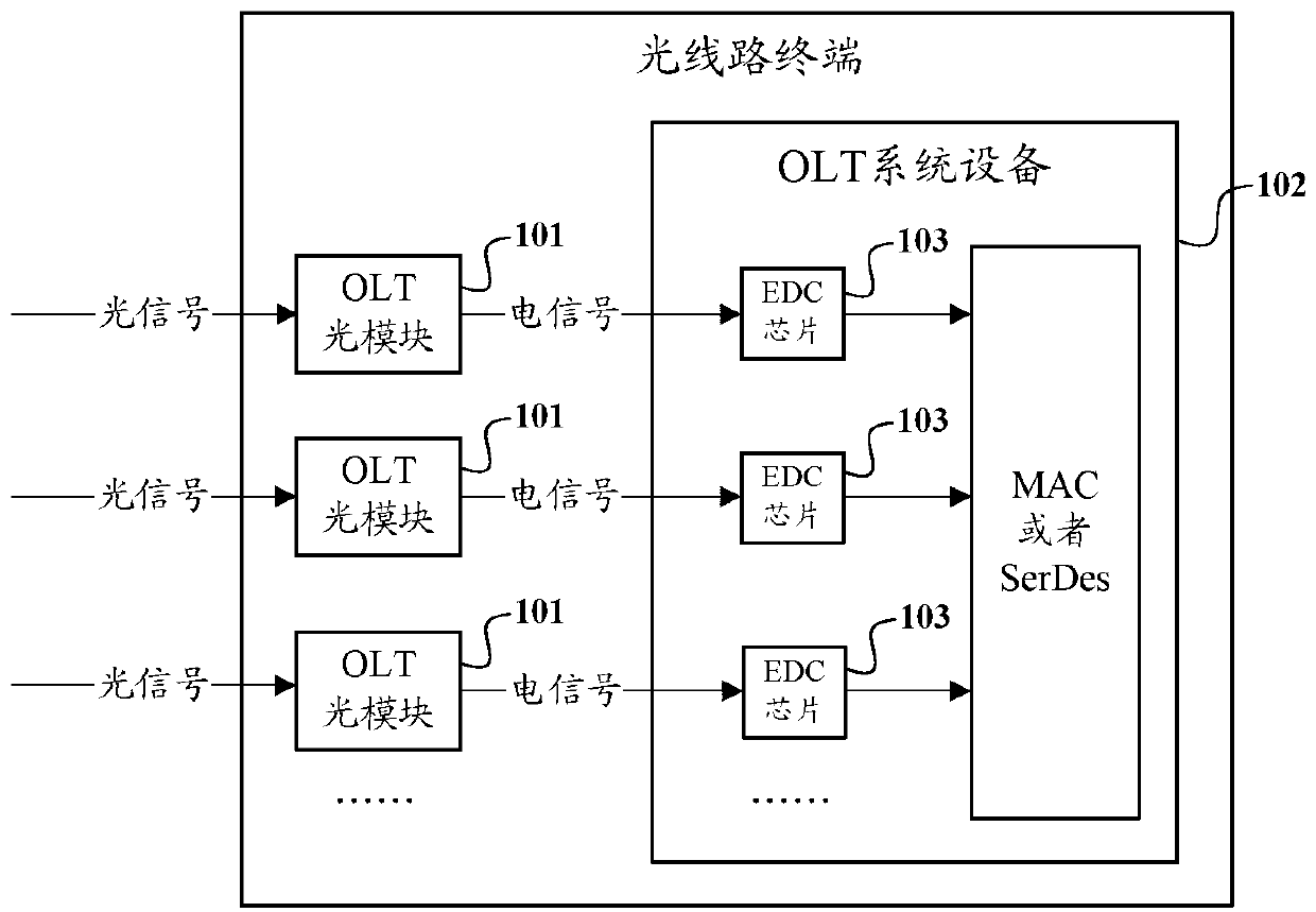
[0008] However, the inventors of the present invention have found that the electrical dispersion compensation method of the prior art is not effective in compensating electrical signals; after analysis, it is found that before the EDC chip in the OLT system equipment performs electrical dispersion compensation on electrical signals, The electr

Method used


Image

  • Optical module and electric domain dispersion compensation method thereof
  • Optical module and electric domain dispersion compensation method thereof
  • Optical module and electric domain dispersion compensation method thereof

Examples


Embodiment Construction

[0055] In order to make the object, technical solution and advantages of the present invention clearer, the present invention will be described in further detail below with reference to the accompanying drawings and preferred embodiments. However, it should be noted that many of the details listed in the specification are only for readers to have a thorough understanding of one or more aspects of the present invention, and these aspects of the present invention can be implemented even without these specific details.

[0056] As used herein, terms such as "module" and "system" are intended to include computer-related entities such as, but not limited to, hardware, firmware, a combination of hardware and software, software, or software in execution. For example, a module may be, but is not limited to being limited to being, a process running on a processor, a processor, an object, an executable, a thread of execution, a program, and / or a computer. For example, both an applicatio...


PUM


Abstract

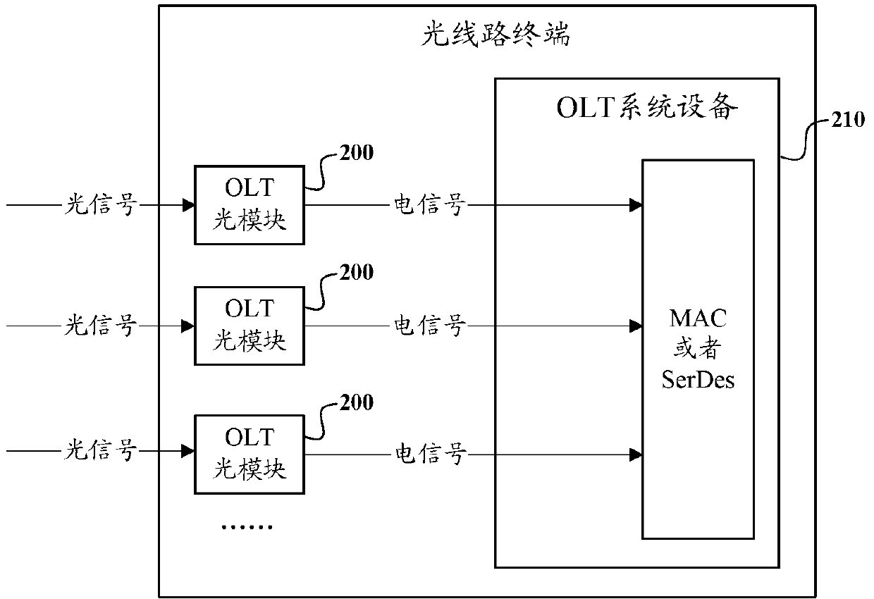
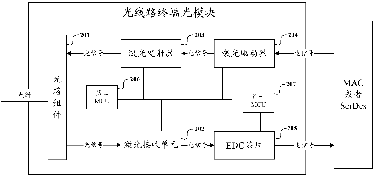
The invention discloses an optical module and an electric domain dispersion compensation method thereof. The optical module comprises an optical path assembly, a laser receiving unit, an EDC chip and a first MCU (microprogrammed control unit); the laser receiving unit receives a downlink optical signal sent from an optical fiber by the optical path assembly, converts the optical signal into an electrical signal and amplifies and outputs the electrical signal to the EDC chip; the EDC chip judges the time delay and distortion of the electrical signal outputted from the laser receiving unit and sends the judged time delay and distortion information to the first MCU; the first MCU computes a dispersion compensation value according to the received time delay and distortion information and outputs the value to the EDC chip; and the EDC chip performs electric domain dispersion compensation on the electrical signal outputted from the laser receiving unit according to the dispersion compensation value and outputs the electrical signal. The EDC chip is arranged in the optical module, and the electrical signal after the photoelectrical conversion is subjected to the electric domain dispersion compensation at the EDC chip in the optical module, so the dispersion compensation effect of the electrical signal is better.

Description

technical field [0001] The invention relates to the technical field of optical fiber communication, in particular to an optical module and an electrical domain dispersion compensation method thereof. Background technique [0002] In the optical fiber transmission system, after the optical signal is transmitted through tens of kilometers or even hundreds of kilometers of optical fiber, chromatic dispersion and polarization mode dispersion will occur. The existence of these dispersion phenomena causes pulse broadening and intersymbol interference of the optical signal. In this way, after the optical signal transmitted by the optical fiber is converted into an electrical signal, a large time delay and distortion will be generated, which will cause a large bit error rate of the signal and limit the transmission capacity and transmission bandwidth of the optical fiber. [0003] At present, for the dispersion phenomenon of optical signals in optical fiber transmission, dispersion ...

Claims


Application Information

Patent Timeline
IPC IPC(8): H04B10/2513H04B10/07
Inventor 杨思更赵其圣李明薛登山张强路磊
Owner HISENSE BROADBAND MULTIMEDIA TECH
Why Eureka
Try Eureka