
Frequency offset estimation method in DVB-T2 system

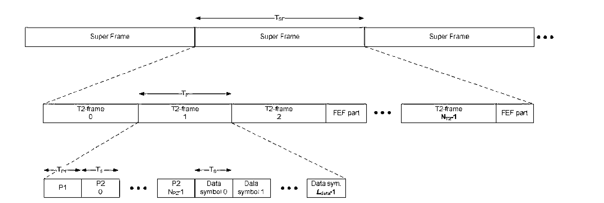
A DVB-T2, coarse frequency offset estimation technology, applied in multi-frequency code systems and other directions

Active Publication Date: 2013-09-04
HUNAN GOKE MICROELECTRONICS
View PDF5 Cites 13 Cited by
  • Summary
  • Abstract
  • Description
  • Claims
  • Application Information

AI Technical Summary

Problems solved by technology

[0028] After the frame synchronization ends, due to certain errors, only the approximate starting position of the T2 frame can be found

Method used


Image

  • Frequency offset estimation method in DVB-T2 system
  • Frequency offset estimation method in DVB-T2 system
  • Frequency offset estimation method in DVB-T2 system

Examples


Embodiment Construction

[0084] The principle of the present invention is further described below with reference to the accompanying drawings.

[0085] 1) Estimation method of residual frequency offset

[0086] a) According to the result of symbol synchronization, take the P1 symbol r of the received signal p1 (n)

[0087] b) According to the results of frame synchronization S1 and S2, generate P1 symbol s p1 (n)

[0088] The generation process of the P1 symbol is as follows:

[0089] After the frame synchronization is locked, two parameters S1 and S2 will be provided. These two parameters indicate the FFT mode and MISO mode adopted by the current system, which determine the content and structure of the frame header P1 symbol of the DVB-T2 system.

[0090] Table 1S1 and S2 modulation modes

[0091]

[0092] As can be seen from the above table, S1 and S2 are 3-bit and 4-bit parameters, corresponding to 8 and 16 possible sequences, respectively. The sequence length corresponding to S1 is 64 bit...


PUM


Abstract

The invention discloses a frequency offset estimation method in a DVB-T2 system. The method includes using a P1 symbol which is generated in a receiver again, relating the P1 symbol with a received signal and reducing the range of residual frequency offset; using time domain information of pilot frequency of a P2 symbol to be related with the received signal, and estimating an integral frequency offset; using the time domain information of the pilot frequency of the P2 symbol to be related with the received signal, and estimating fractional frequency offsets; calculating the fractional frequency offsets for many times and obtaining an average value of the fractional frequency offsets for improvement of accuracy. Due to the fact that multiple fractional frequency offsets are calculated and the average value is obtained, the accuracy of estimation is improved. The method avoids relative complex calculation in a 16K and 32K mode of the integral frequency offset, and improves detection speed and estimation precision of the integral frequency offset.

Description

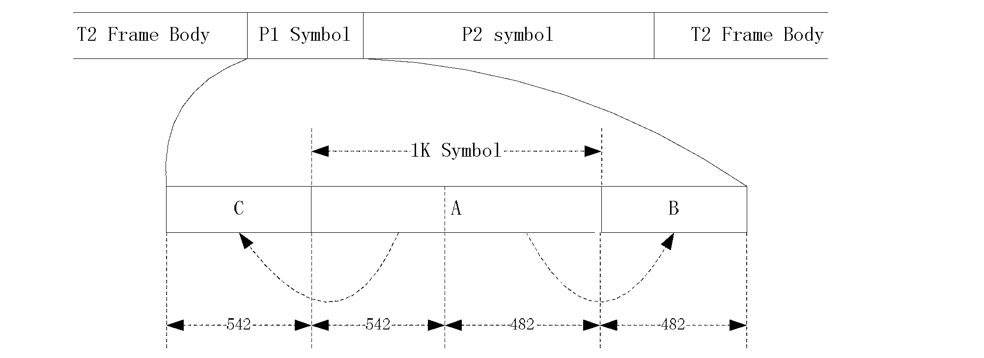
technical field [0001] The present invention relates to a method for estimating integer frequency offset and fractional frequency offset suitable for DVB-T2 system, multi-carrier system based on OFDM system, such as DVB-T, DTMB and other systems. Background technique [0002] DVB-T2 system is a terrestrial digital TV broadcasting system based on OFDM multi-carrier technology. Its baseband signal is divided into superframes one by one. Each superframe contains up to 255 T2 frames. Start with the P1 symbol bit, followed by N P2 symbols, followed by a number of data symbols, where both the P2 symbols and the data symbols have the same FFT length and guard interval (GI) length. [0003] The structure of the P1 symbol is fixed, with a length of 2048, figure 2 As can be seen from the above, part A is obtained by 1K IFFT after encoding S1 and S2, and C and B are weighted copies of the first and second half of A, respectively. The generation process is shown in image 3 . [0004...

Claims


Application Information

Patent Timeline
IPC IPC(8): H04L27/26
Inventor 朱志敏
Owner HUNAN GOKE MICROELECTRONICS
Learn More