Collocation method of novel type carrier wave, base station and user terminal
A new type of carrier and user terminal technology, applied in electrical components, wireless communication, network planning, etc., can solve the problem that LTE user terminals cannot use non-backward compatible carriers, and achieve the effect of improving data rate and system capacity
- Summary
- Abstract
- Description
- Claims
- Application Information
AI Technical Summary
Problems solved by technology
Method used
Image
Examples
Embodiment 1
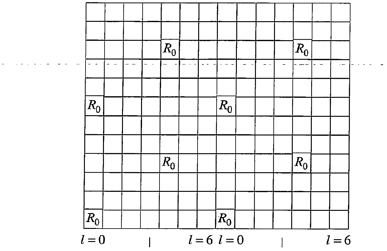
[0070] Figure 2a It is a configuration pattern in which the system bandwidth of the new type carrier is equal to 1.4 MHz. As shown in the figure, the cell reference signal is configured on 4 subframes in one radio frame, and its configured bandwidth is the entire system bandwidth, that is, 1.4 MHz.
[0071] It can be further seen from the figure that the cell reference signal is specifically configured on a subframe (Subframe, SF) {#0, #1, #5, #6} in a radio frame; where subframe #0 and subframe #1, Subframe #5 and subframe #6 are adjacent to form two adjacent subframe pairs, and the time interval between two adjacent subframe pairs is exactly half of the length of a radio frame.
[0072] The benefit of this configuration is that the duration interval between two adjacent subframes is smaller than the coherence time of the wireless propagation environment and is the smallest among all subframes, which helps to improve the performance of time-frequency tracking; The interval...
Embodiment 2
[0077] Figure 3a It is a configuration pattern in which the system bandwidth of the new type carrier is equal to 5 MHz. As shown in the figure, the cell reference signal is configured on two subframes in one radio frame, and its configured bandwidth is the entire system bandwidth. It can be further seen from the figure that the cell reference signal is specifically configured on the subframe {#0, #5} in a radio frame; the time interval between two configured subframes is exactly half of the length of a radio frame.
[0078] As mentioned above, setting the interval between two configuration subframes to half of the radio frame length helps average sampling in one radio frame to improve the performance of physical signal measurement. On the condition that this premise is met, the subframe configuration in this embodiment is not limited to subframes {#0, #5}, and there are options such as subframes {#1, #6}, subframes {#4, #9}, etc.
[0079] Figure 3b shown in Figure 3a Th...
Embodiment 3
[0083] Figure 4a It is another configuration pattern in which the system bandwidth of the new type carrier is equal to 5MHz. As shown in the figure, the cell reference signal is configured on a subframe {#0, #1} in a radio frame, that is, a group of adjacent subframe pairs, and its configured bandwidth is the entire system bandwidth.
[0084] As mentioned above, configuring the cell reference signal on a group of adjacent subframe pairs helps to improve time-frequency tracking performance. On the condition that this premise is met, the subframe configuration in this embodiment is not limited to subframes {#0, #1}, and there are options such as subframes {#5, #6}, subframes {#8, #9}, etc.
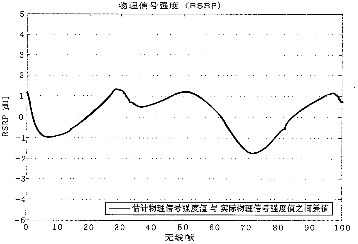
[0085] Figure 4b shown in Figure 4a The performance of physical signal measurement under configuration;
[0086] Figure 4c shown in Figure 4a Configure the performance of time-frequency tracking;
[0087] From Figure 4band Figure 4c It can be seen that all can meet the requir...
PUM
 Abstract
Description
Claims
Application Information
 - R&D
- Intellectual Property
- Life Sciences
- Materials
- Tech Scout
- Unparalleled Data Quality
- Higher Quality Content
- 60% Fewer Hallucinations
Browse by: Latest US Patents, China's latest patents, Technical Efficacy Thesaurus, Application Domain, Technology Topic, Popular Technical Reports.
© 2025 PatSnap. All rights reserved.Legal|Privacy policy|Modern Slavery Act Transparency Statement|Sitemap|About US| Contact US: help@patsnap.com


