

Droplet micro-fluidic chip and operation method thereof
A microfluidic chip and droplet technology, applied in chemical instruments and methods, laboratory utensils, chemical/physical/physicochemical processes, etc., can solve problems that are difficult to achieve precise control, expensive, flow field stability and uniformity and other issues, to achieve the effect of mild splitting and fusion conditions
- Summary
- Abstract
- Description
- Claims
- Application Information
AI Technical Summary
Problems solved by technology
Method used
Image

Examples
Embodiment 1
[0020] Example 1 A microfluidic chip for droplet generation
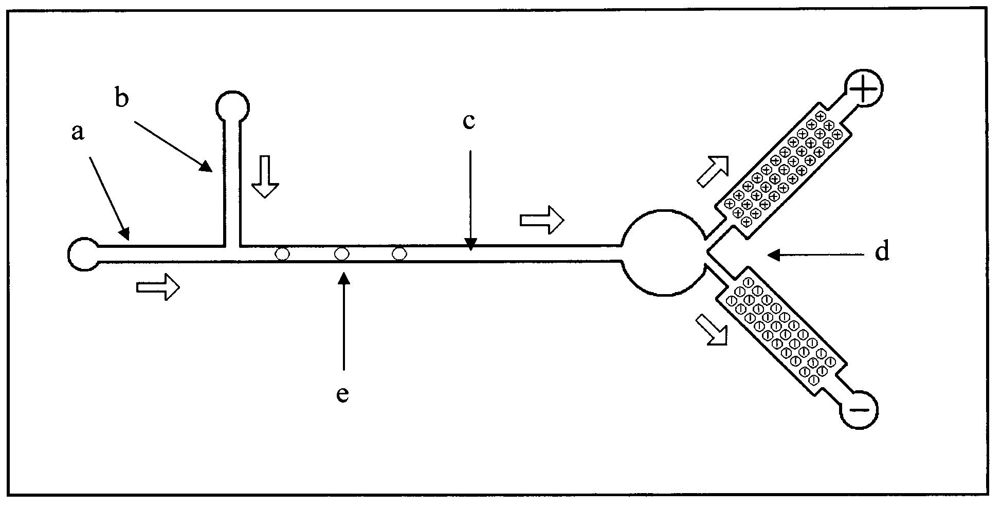
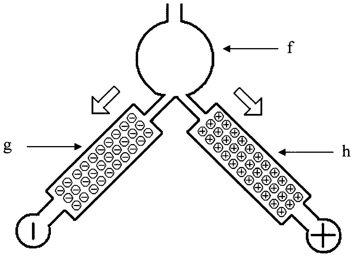
[0021] A microfluidic chip structure for droplet generation such as figure 1 As shown, the microfluidic chip is made of glass, and the width and depth of channels a, b and c are 200 microns and 80 microns respectively. The structure of the electroosmotic pump d is as follows figure 2 As shown, the electroosmotic pump contains a confluence buffer f and two Y-shaped intersected packed column channels g and h. The two filled column channels are filled with glass microspheres with a particle size of 5 microns, and the surfaces are respectively modified with positive and negative charges. .
[0022] During the experiment, firstly, the internal channel of the chip is filled with 0.1M borax buffer solution, the filled column g of the electroosmotic pump is connected to the negative electrode of the external electric field, and the filled column h is connected to the positive electrode of the external electric field. Und...
Embodiment 2
[0023] Example 2 A microfluidic chip for droplet splitting
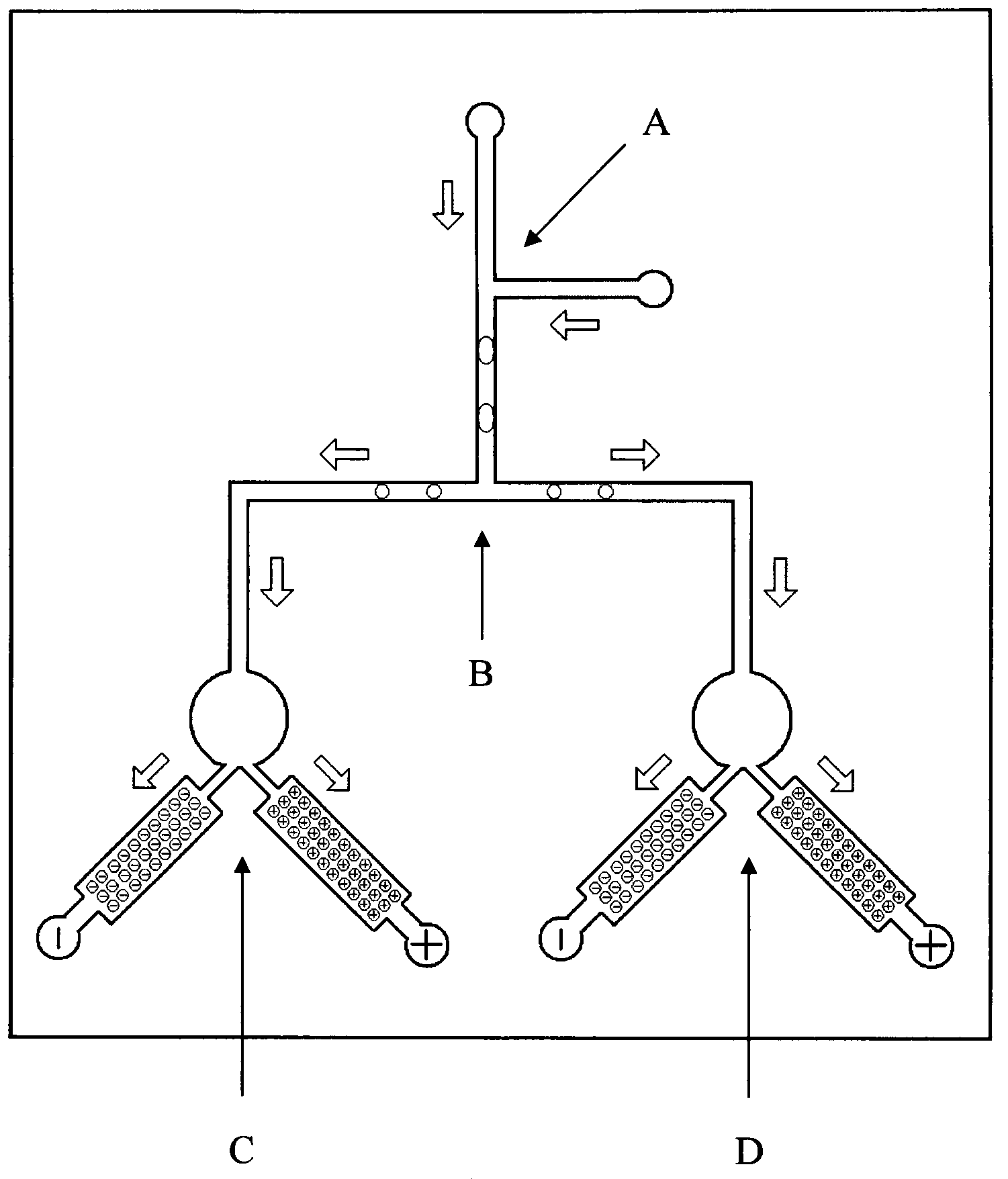
[0024] A microfluidic chip structure for droplet splitting such as image 3 As shown, the microfluidic chip is made of polycarbonate, and the chip includes a droplet generation channel A, a droplet splitting channel B and two electroosmotic pumps C and D. Wherein, the droplet splitting channel B is composed of two branch channels, and the electroosmotic pumps C and D are respectively connected to the two branch channels of the splitting channel B. All channels have a width and depth of 200 μm and 80 μm. The structural composition of electroosmotic pumps C and D is as follows figure 2 As shown, the electroosmotic pump contains a confluence buffer f and two Y-shaped intersected packed column channels g and h. The two filled column channels are filled with glass microspheres with a particle size of 5 microns, and the surfaces are respectively modified with positive and negative charges. .
[0025] During the experi...
Embodiment 3
[0026] Example 3 A microfluidic chip for droplet fusion
[0027] A microfluidic chip structure for droplet fusion such as Figure 4 As shown, the microfluidic chip is made of polydimethylsiloxane, and the chip includes two droplet generation channels E and F, a droplet fusion channel G and an electroosmotic pump H. Wherein, the droplet fusion channel G is formed by the intersection of two channels, and the electroosmotic pump H is connected to the intersection channel of the fusion channel. All channels have a width and depth of 200 μm and 80 μm. The structural composition of electroosmotic pumps C and D is as follows figure 2 As shown, the electroosmotic pump contains a confluence buffer f and two Y-shaped intersected packed column channels g and h. The two filled column channels are filled with glass microspheres with a particle size of 5 microns, and the surfaces are respectively modified with positive and negative charges. .
[0028] During the experiment, firstly, th...
PUM
| Property | Measurement | Unit |
|---|---|---|
| Particle size | aaaaa | aaaaa |
| Particle size | aaaaa | aaaaa |
Abstract
Description
Claims
Application Information