Valve seat ring distributing mechanism
A valve seat ring and distribution mechanism technology, applied in the field of machinery, can solve the problems of high equipment cost and operation and maintenance cost, increased labor cost, and need for special care, and achieve no maintenance cost, simple structure, and low production cost Effect
- Summary
- Abstract
- Description
- Claims
- Application Information
AI Technical Summary
Problems solved by technology
Method used
Image
Examples
Embodiment 1
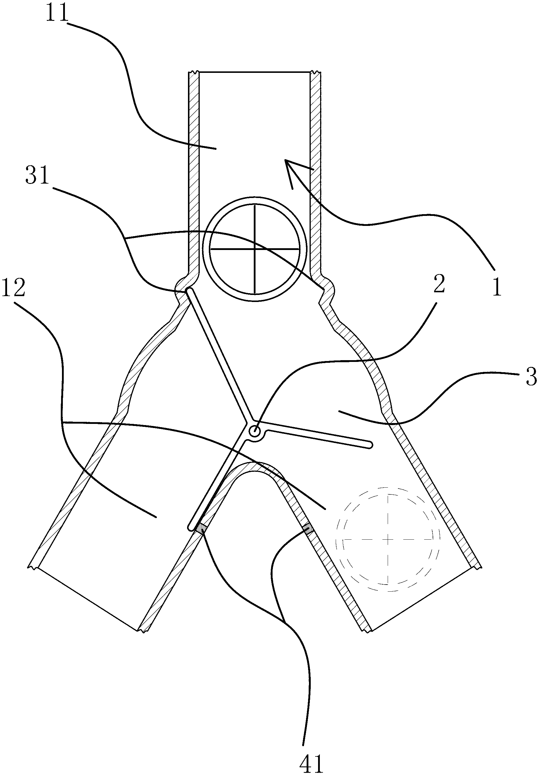
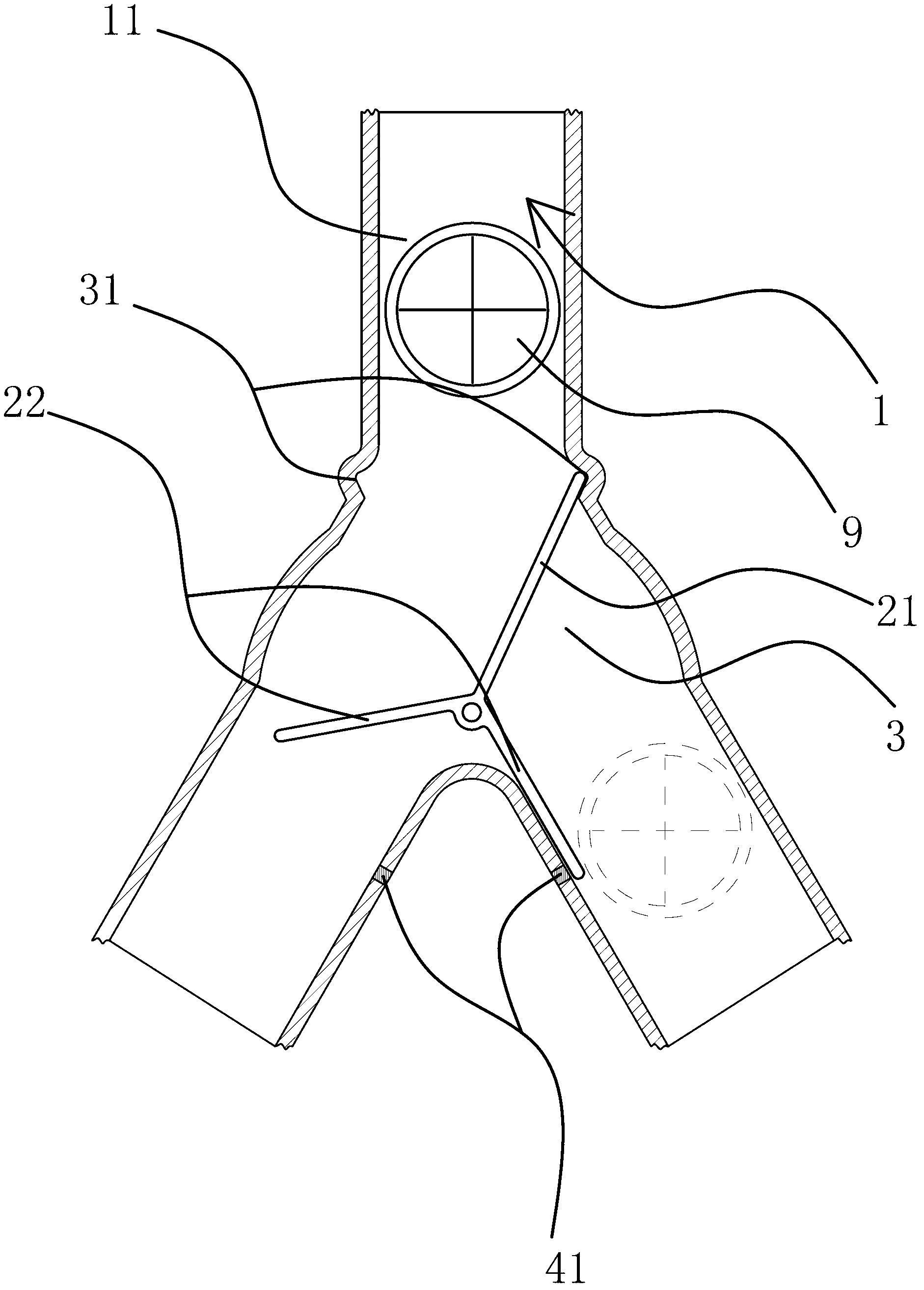
[0034] Such as figure 1As shown, the distribution mechanism includes a trident pipe 1, the trident pipe 1 has a feed branch pipe 11 and two discharge branch pipes 12, the outlet of the feed branch pipe 11 is connected to the inlet of the two discharge branch pipes 12 and formed at the junction A joint part 3 is provided with a distribution frame 2 hinged on the inner wall of the trident pipe 1 at the joint part 3, and the distribution frame 2 can be intermittently opened and closed by the inertial force of the valve seat ring 9 when it descends. Inlet, before using this distribution mechanism, the two discharge branch pipes 12 of the trident pipe 1 are respectively aligned with the two valve seat ring installation holes of the engine block, when the first valve seat ring 9 descends from the feed branch pipe 11 , the distribution rack 2 blocks one of the discharge branch pipes 12, when the second valve seat 9 descends from the feed branch pipe 11 to the junction 3, due to the a...
Embodiment 2
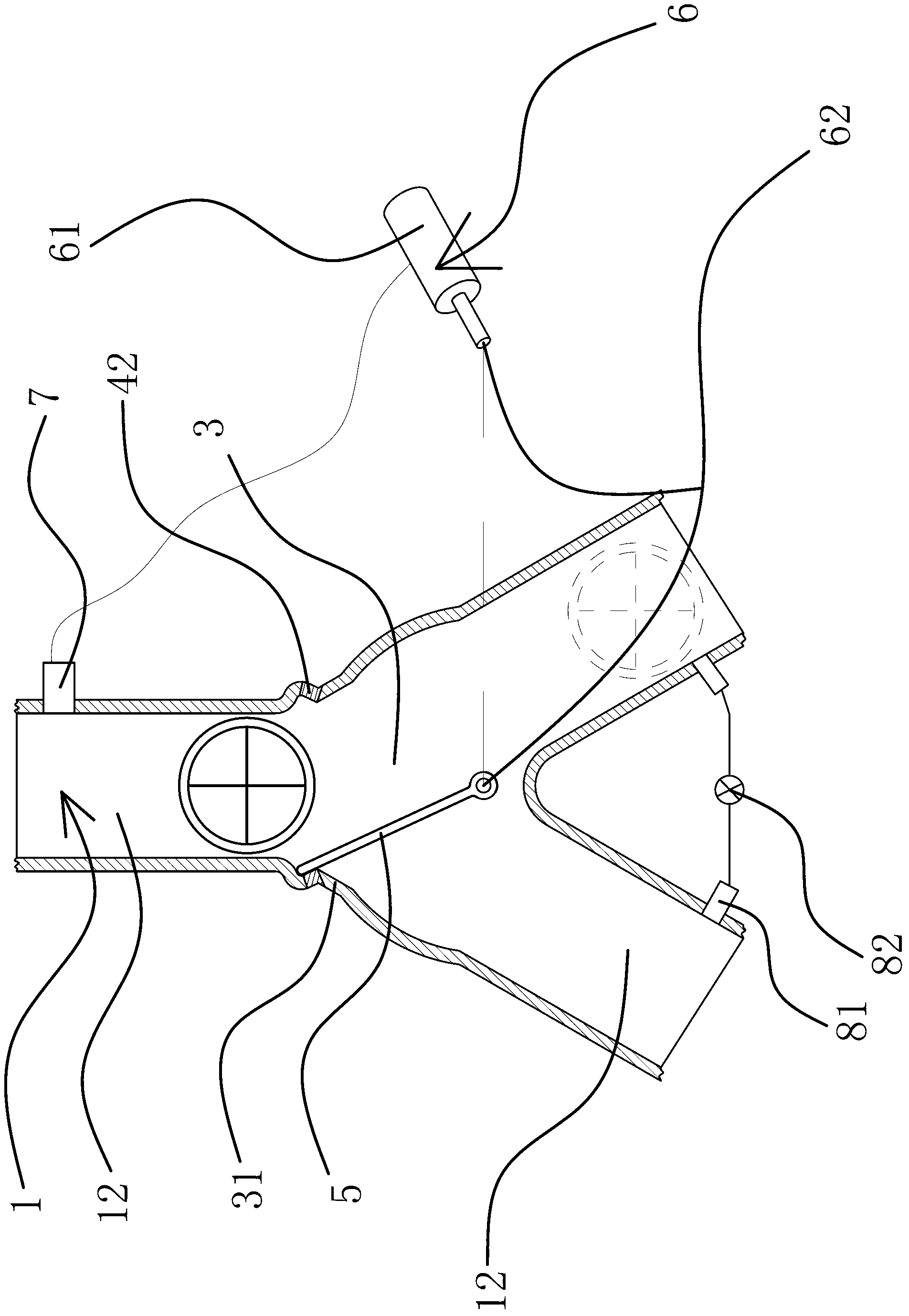
[0039] Such as image 3 As shown, the distribution mechanism includes a trident pipe 1, the trident pipe 1 has a feed branch pipe 11 and two discharge branch pipes 12, the outlet of the feed branch pipe 11 is connected to the inlet of the two discharge branch pipes 12 and formed at the junction A combination part 3, a baffle plate 5 is arranged inside the combination part 3, and the baffle plate 5 is connected to a drive assembly 6 capable of intermittently driving the baffle plate 5 to open and close the inlet of the discharge branch pipe 12. Before using the distribution mechanism, The two discharge branch pipes 12 of the trident pipe 1 are respectively aligned with the two valve seat ring mounting holes of the engine block. When the first valve seat ring 9 descends from the feed branch pipe 11, the drive assembly 6 drives the baffle plate 5 Block one of the discharge branch pipes 12, when the second valve seat ring 9 descends from the feed branch pipe 11, the drive assembly...
Embodiment 3
[0043] Such as Figure 4 with Figure 5 As shown, the present embodiment is based on embodiment one or embodiment two, and the valve seat ring 9 is a gasket installed on the intake valve and the outlet valve on the engine block. Taking a four-cylinder engine as an example, If each cylinder is correspondingly provided with two intake valves and one outlet valve, in order to install all valve seat rings 9 at one time, a plurality of above-mentioned trident pipes 1 can be connected. In this embodiment, three Trident pipe 1 is taken as an example to illustrate the principle of this scheme: the feed branch pipes 11 of two trident pipes 1 are connected with the two discharge branch pipes 12 of the other trident pipe 1 respectively, and the three trident pipes are generally connected by welding. Connect the pipes 1 and let them all communicate with each other. Align the four outlet pipes 12 at the bottom with the valve seat ring mounting holes on the engine block, and put down the f...
PUM
 Abstract
Description
Claims
Application Information
 - R&D Engineer
- R&D Manager
- IP Professional
- Industry Leading Data Capabilities
- Powerful AI technology
- Patent DNA Extraction
Browse by: Latest US Patents, China's latest patents, Technical Efficacy Thesaurus, Application Domain, Technology Topic, Popular Technical Reports.
© 2024 PatSnap. All rights reserved.Legal|Privacy policy|Modern Slavery Act Transparency Statement|Sitemap|About US| Contact US: help@patsnap.com


