

A continuous casting device and a continuous casting method for continuously casting castings formed by magnesium or magnesium alloys
A technology for magnesium alloys and castings, applied in the field of continuous casting devices, can solve problems such as the inability to stabilize continuous casting of magnesium alloys, and achieve the effects of improving casting quality, preventing involvement and improving casting quality
- Summary
- Abstract
- Description
- Claims
- Application Information
AI Technical Summary
Problems solved by technology
Method used
Image

Examples
no. 1 approach
[0092] Below, refer to Figure 1 to Figure 5 The first embodiment of the present invention will be described. Hereinafter, first, a specific example of the conventional art related to the first embodiment of the present invention will be described in detail, and then a specific configuration will be described.
[0093] [Specific examples of prior art]
[0094] Conventionally, for example, a horizontal continuous casting apparatus for continuously casting a magnesium alloy casting is disclosed in Reference 1 (JP-A-2011-173148).
[0095] Such as Figure 4 As shown, the continuous casting device 1410 disclosed in Reference 1 includes: a melting furnace (not shown), a holding furnace 1420, a pressurizing device 1430, a molten metal supply pipe 1440, a drain 1450, a mold mounting plate 1460, and a mold for continuous casting. 1470. Pulling device 1480. Among them, a cover plate 1452 made of stainless steel that shields the molten metal from the atmosphere is provided at the ope...
no. 2 approach
[0155] Below, refer to Figure 6 ~ Figure 10 A second embodiment of the present invention will be described. Hereinafter, first, a specific example of the prior art related to the second embodiment of the present invention will be described in detail, and then a specific configuration will be described.
[0156] [Specific examples of prior art]
[0157] Conventionally, in continuous casting equipment, there are various configurations of molten metal supply pipes used for supplying molten metal stored in a holding furnace to a sink. A molten metal supply pipe with the following structure for supplying molten metal.
[0158] Such as Figure 10 As shown, the molten metal supply pipe 2101 of Reference 3 supplies the molten metal M sent from the molten metal discharge part 2131 to the die casting sleeve 2141 in the die casting casting device 2111 . Furthermore, the molten metal discharge part 2131 is provided with a base plate 2134 and an injection sleeve 2132, and is suspended...
no. 3 approach
[0215] Below, refer to Figure 11 ~ Figure 17 A third embodiment of the present invention will be described. Hereinafter, first, a specific example of the prior art related to the third embodiment of the present invention will be described in detail, and then a specific configuration will be described.
[0216] [Specific examples of prior art]
[0217] Conventionally, a sink used in continuous casting equipment for magnesium alloys has electric heaters built into the bottom wall and side walls in order to maintain the temperature of the accumulated molten metal, as disclosed in reference 4 (Japanese Patent No. 3668245), for example.
[0218] However, with regard to the cleaning of the drain tank where the magnesium alloy molten metal is accumulated, when casting alloys of different types, in order to avoid the residue of the alloy components used last time, it is necessary to clean the inner peripheral surface of the drain tank by washing with water. magnesium alloy for clea...
PUM
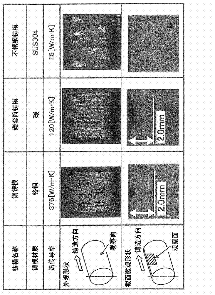
| Property | Measurement | Unit |
|---|---|---|
| Thermal conductivity | aaaaa | aaaaa |
| Thermal conductivity | aaaaa | aaaaa |
| Diameter | aaaaa | aaaaa |
Abstract
Description
Claims
Application Information