Special fixture for processing steam turbine generator rotor coil ventilation hole

A technology of steam turbine generator and rotor coil, which is applied in the direction of manufacturing tools, metal processing equipment, metal processing machinery parts, etc. The effect of pollution, high production efficiency and fast clamping action

Active Publication Date: 2015-08-19
HARBIN ELECTRIC MASCH CO LTD
View PDF5 Cites 0 Cited by
  • Summary
  • Abstract
  • Description
  • Claims
  • Application Information

AI Technical Summary

Problems solved by technology

Using manual mechanical clamping method, the operator has high labor intensity, frequent movements, and low production efficiency; using hydraulic clamping method, there is a hidden danger of oil leakage. Once oil leaks, it will cause pollution to the coil surface and affect the quality of the coil.

Method used


Image

  • Special fixture for processing steam turbine generator rotor coil ventilation hole
  • Special fixture for processing steam turbine generator rotor coil ventilation hole
  • Special fixture for processing steam turbine generator rotor coil ventilation hole

Examples


Embodiment Construction

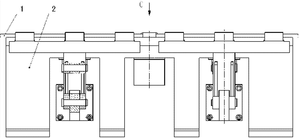
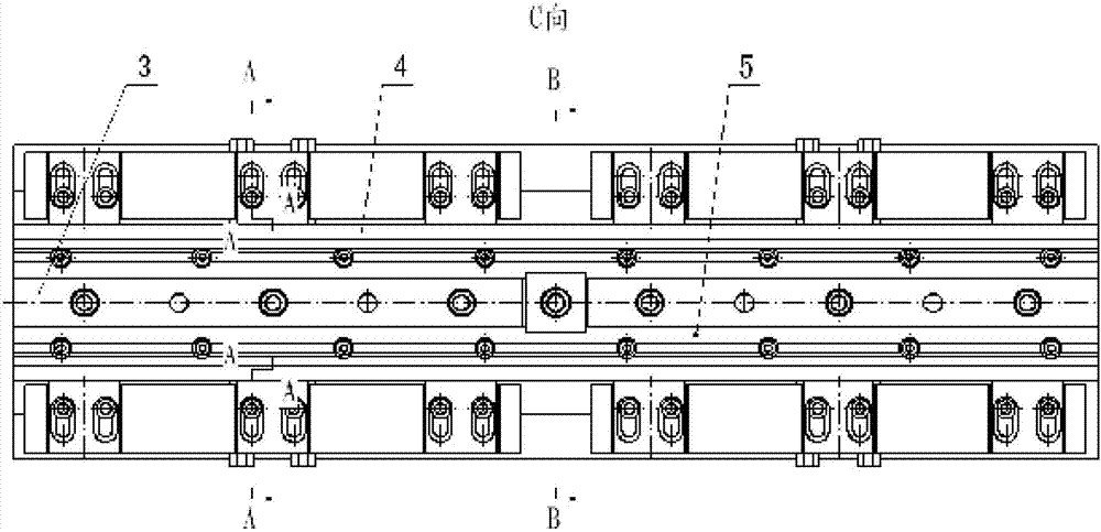
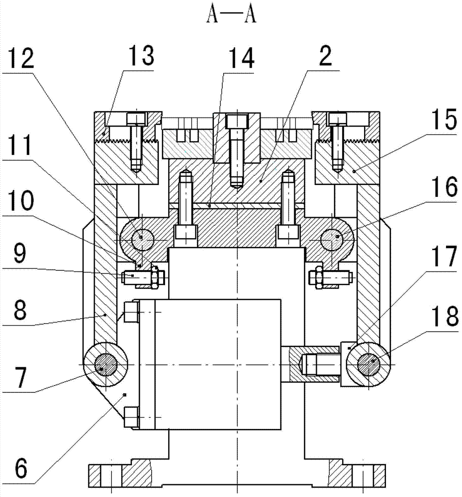
[0018] like figure 1 , figure 2 , image 3 , Figure 4 As shown, a special jig for machining ventilation holes of the rotor coil of a turbogenerator is composed of a rotor coil 1, a base 2, a positioning block 3, a first mold base 4, a second mold base 5, a side pressure cylinder 6, and a pin I7. , left swing rod 8, limit block 9, support seat 10, lock nut 11, pin shaft II 12, side pressure head 13, adjustment pad I 14, right swing rod 15, pin shaft III 16, joint 17, pin shaft IV 18, upper Press head 19, bolt 20, adjustment pad II 21, upper pressure cylinder 22 and other main components. like figure 1 , figure 2 As shown, the two rotor coils 1 are placed on the first mold base 4 and the second mold base 5 respectively, separated and positioned by the positioning block 3, the first mold base 4, the second mold base 5 and the positioning block 3 are respectively installed on the base 2, two left swing rods 8 and two right swing rods 15 are respectively installed on both ...


PUM


Abstract

The invention discloses a fixture for steam turbine generator rotor coil vent hole machining. Two rotor coils are placed flat on a left die holder and a right die holder respectively, and are separated and positioned by a positioning check block. A lateral pressing air cylinder piston rod stretches out and draws back to drive a movable fulcrum pin shaft of a left oscillating bar and a movable fulcrum pin shaft of a right oscillating bar to motion, so that the left oscillating bar is driven to swing around a fixed fulcrum pin shaft of the left oscillating bar, and the right oscillating bar is driven to swing around a fixed fulcrum pin shaft of the right oscillating bar. A limiting block on the left side and a limiting block on the right side limit an opening of the left oscillating bar and an opening of the right oscillating bar to be consistent in size. The left rotor coil and the right rotor coil are tightly pressed or loosened at the same time through a lateral pressing head. An upward pressing air cylinder piston rod stretches out and draws back to drive an upward pressing head to move in a reciprocating mode along a positioning check block guide hole, so that the left rotor coil and the right rotor coil are loosened or tightly pressed in the vertical direction. The fixture for the steam turbine generator rotor coil vent hole machining is high in automation degree, high in work efficiency, strong in universality, simple in structure, reliable in operation, long in service life, and capable of greatly mitigating the labor intensity for an operator.

Description

Technical field: [0001] The invention relates to a special jig for machining ventilation holes of a steam turbine generator rotor coil. Background technique: [0002] The turbo generator rotor coil is one of the most important components in the turbo generator set. The number of rotor coils, the length of the coils, the width of the coils, the thickness of the coils, and the number of ventilation holes are different for units with different power generation. The number of coils per unit is about 300-700, the length of the coil is about 5-10 meters, the width of the coil is about 28-50 mm, the thickness of the coil is about 5-15 mm, and the number of ventilation holes on a single coil There are about 100 to 200 pieces. It can be seen that there are many kinds of coils and the amount of ventilation holes is huge. At present, the processing of the ventilation holes of the rotor coil by the relevant domestic production plants adopts the method of placing the rotor coil vertica...

Claims


Application Information

Patent Timeline
Patent Type & Authority Patents(China)
IPC IPC(8): B23Q3/00
Inventor 杨宏伟张宁刘雅兰李冰肖军刘敏李崒
Owner HARBIN ELECTRIC MASCH CO LTD
Why Eureka
Try Eureka