Main shaft lubricating mechanism of straight buttonhole machine

A technology of lubricating mechanism and buttonhole machine, which is used in lubrication/cooling devices, sewing machine components, textiles and papermaking, etc., can solve the problems of inability to reuse lubricating oil, increase maintenance costs, add lubricating oil, etc., and achieve enhanced deformation resistance. , good lubricating effect, increase the effect of lubricating

Inactive Publication Date: 2013-09-11
浙江银工缝制设备有限公司
View PDF6 Cites 2 Cited by
  • Summary
  • Abstract
  • Description
  • Claims
  • Application Information

AI Technical Summary

Problems solved by technology

Although the lubricating structure of this structure can reduce the wear of the transmission spindle, it needs to add lubricating oil artificially, and the lubricating oil cannot be reused, and the rough drill will also be worn, which also increases the maintenance cost

Method used


Image

  • Main shaft lubricating mechanism of straight buttonhole machine
  • Main shaft lubricating mechanism of straight buttonhole machine
  • Main shaft lubricating mechanism of straight buttonhole machine

Examples


Embodiment 1

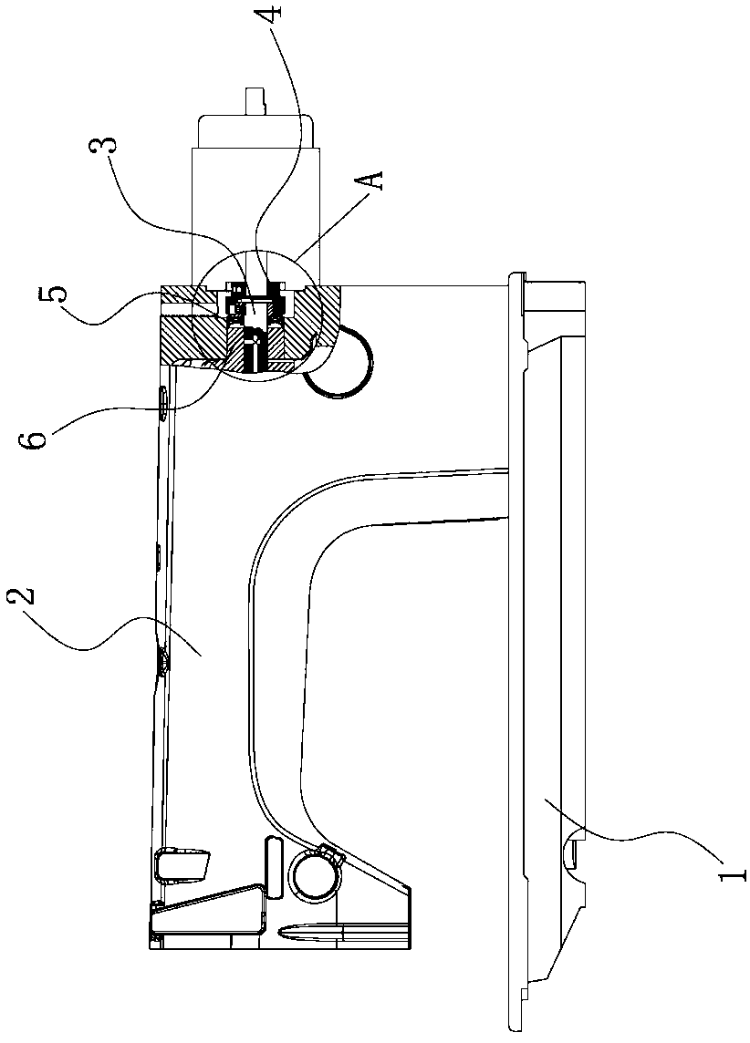
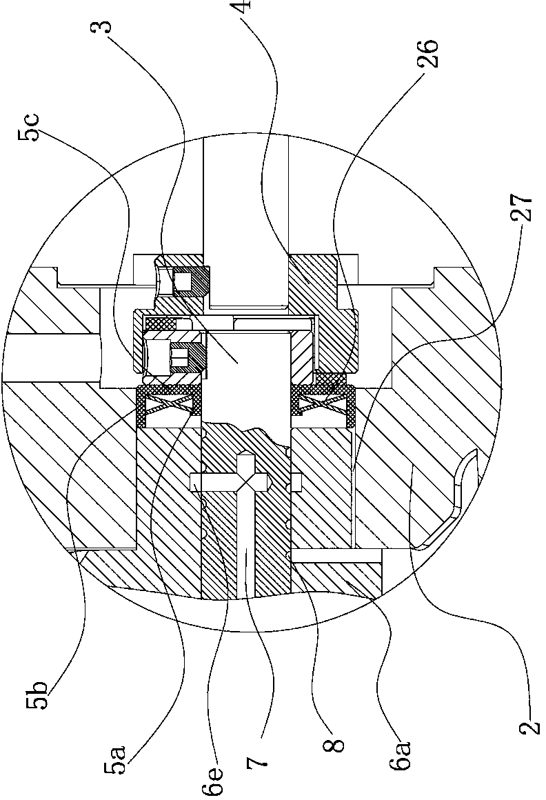
[0025] Such as figure 1 , figure 2 , image 3 , Figure 4 or Figure 5 As shown, the main shaft lubrication mechanism of the flat head buttonhole machine, the flat head buttonhole machine is mainly composed of a base 1, a machine head housing 2 is fixed on the base 1, and a main shaft 3 is fixed inside the machine head housing 2. One end of the main shaft 3 passes through the machine head housing 2 and the extended end of the main shaft 3 is directly connected with the motor rotor 4 and driven by the motor rotor 4 to rotate. There is an oil seal 5, and the preferred solution of the oil seal 5 is: the oil seal 5 includes an inner ring surface 5a, an outer ring surface 5b, and is connected to the inner ring surface 5a, the outer ring surface 5b and integrally formed with the inner ring surface 5a, the outer ring surface 5b The connection plate surface 5c, the inner ring surface 5a and the outer ring surface 5b are parallel to each other, and a set is provided between...

Embodiment 2

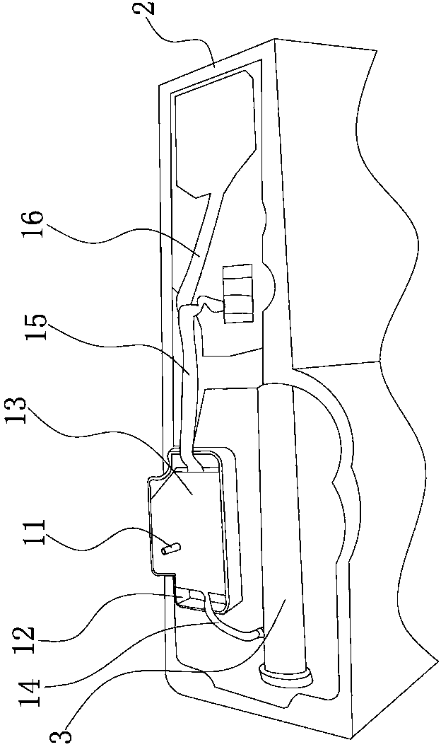
[0030] as shown in the picture Figure 6 As shown, the structure of this embodiment is basically the same as that of Embodiment 1, the difference is that the elastic structure includes a U-shaped strip plate 23, a spring groove 24 is arranged on the U-shaped strip plate 23, and The outer end face of the plunger 18 is provided with a blind hole 21, the blind hole 21 is opposite to the notch of the spring groove 24 of the U-shaped strip plate 23, and a spring 25 is arranged in the blind hole 21, and one end of the spring 25 leans against the blind hole. In the hole 21 , the other end abuts against the aforementioned spring groove 24 .


PUM


Abstract

The invention provides a main shaft lubricating mechanism of a straight buttonhole machine and belongs to the technical field of mechanical equipment. The main shaft lubricating mechanism solves the problems that lubricating oil needs to be supplied manually and the lubricating oil can not be reused in an existing main shaft lubricating structure. The main shaft lubricating mechanism of the straight buttonhole machine is characterized in that a main shaft is fixedly arranged in a machine head shell, an oil seal is arranged between the main shaft and the machine head shell, an oil supply sleeve which is integrally formed by an eccentric wheel and an oil supply sleeve body is connected to the portion, located at the inner end of the oil seal, of the main shaft in a sleeved mode, an oil drive structure which absorbs oil from an oil inlet and supplies the oil to an oil outlet through vacuum is arranged between the main shaft and the eccentric wheel, an oil outlet channel is formed in the main shaft, an annular oil storage chute is formed in the inner wall of the eccentric wheel, the opening of an oil return chute is attached to the inner wall of the eccentric wheel, and the oil return chute is communicated with an inner cavity of the machine head shell. The main shaft lubricating mechanism of the straight buttonhole machine has the advantages of being low in work noise, simple in structure, long in service life and the like.

Description

technical field [0001] The invention belongs to the technical field of mechanical equipment, and relates to a main shaft lubricating mechanism of a flat buttonhole machine. Background technique [0002] Buttonhole sewing machine is a very important equipment in sewing machine machinery. Buttonhole sewing machine is referred to as buttonhole machine for short. The buttonhole machine is mainly used to process buttonholes in various clothing. two kinds. During the sewing process, the needle bar of the flat-head buttonhole machine not only moves up and down, but also moves horizontally, so that the sewing needle can penetrate the sewing material at different positions of the needle plate hole, and realize left row and right row , front and rear bartacks for complete buttonhole sewing. The swing performance of the needle bar is very important to the stability of the buttonhole machine. Whether the swing range of the needle bar is reasonable and stable is directly related to the...

Claims


Application Information

Patent Timeline
Patent Type & Authority Applications(China)
IPC IPC(8): D05B71/00
Inventor 叶朋成
Owner 浙江银工缝制设备有限公司
Why Eureka
Try Eureka