Adhesive applicator/coater

A technology of applicator and rubber strip, applied in the direction of paper, etc., can solve the problems of low smoothness, coating marks, clogging, etc.

Inactive Publication Date: 2013-09-11
HANGZHOU PROJECT & RES INST OF ELECTRO MECHANIC & LIGHT IND
View PDF0 Cites 4 Cited by
  • Summary
  • Abstract
  • Description
  • Claims
  • Application Information

AI Technical Summary

Problems solved by technology

However, this type of coating machine has low smoothness and poor surface smoothness. The concentration and viscosity of the coating cannot be used for high-

Method used


Image

  • Adhesive applicator/coater
  • Adhesive applicator/coater

Examples


Embodiment Construction

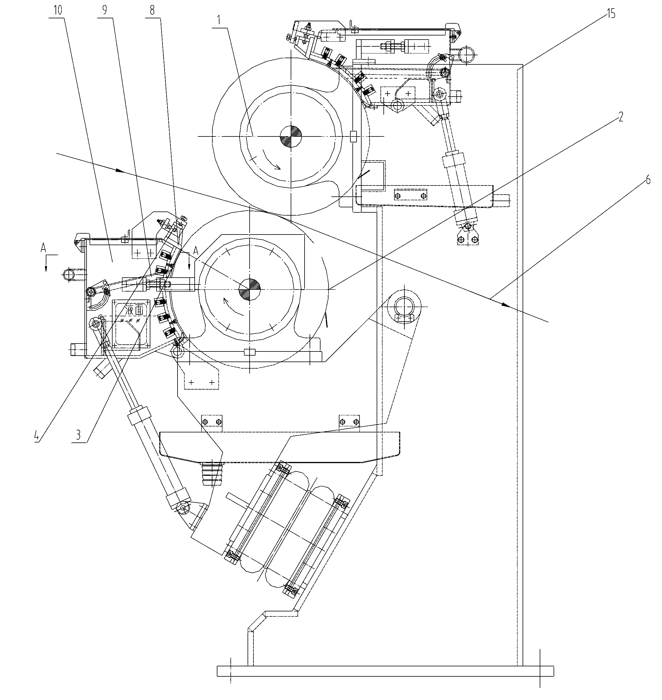
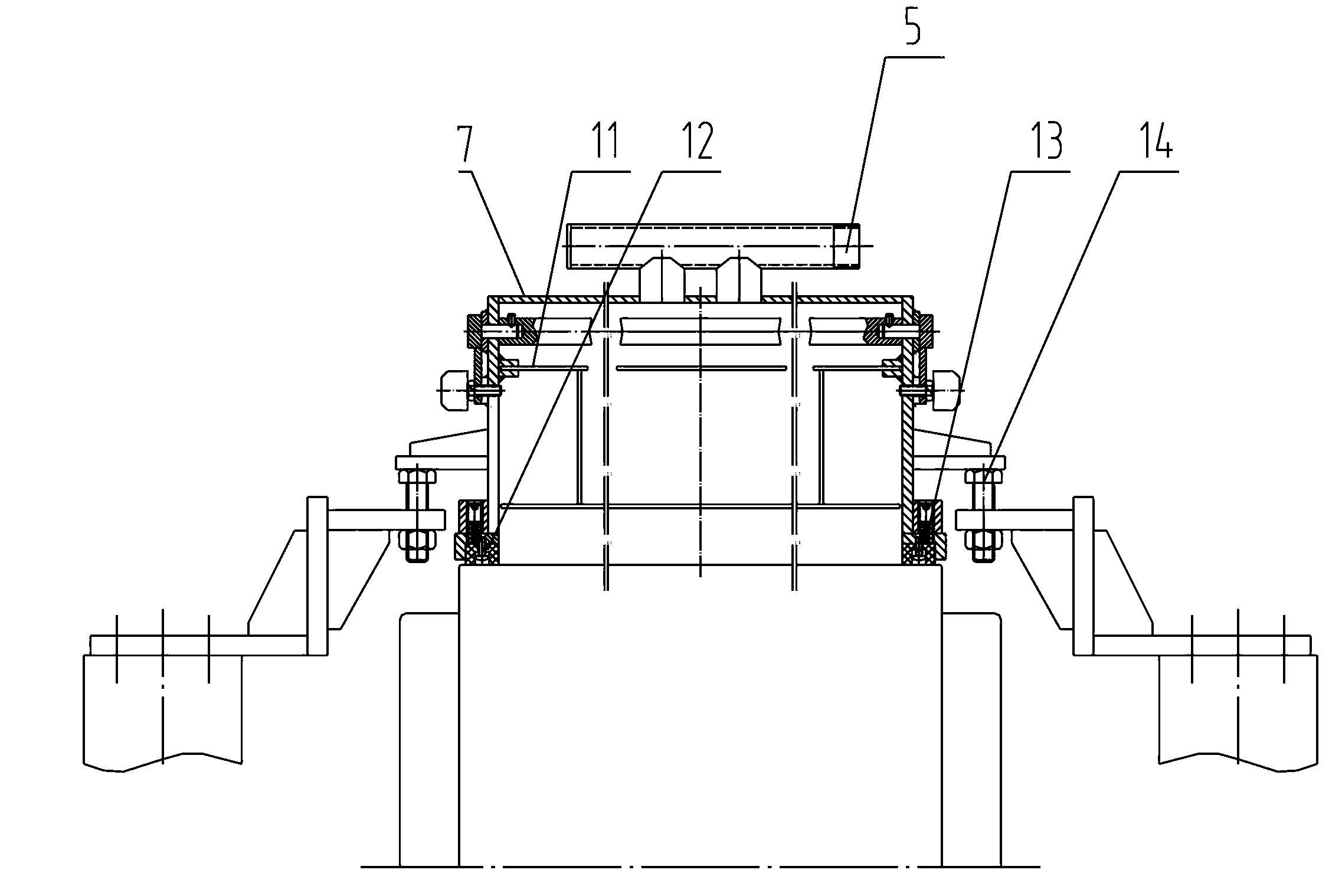
[0013] A size / applicator such as figure 1 , figure 2 Shown, comprise frame 15 and two coating rolls 1, paper web 6 is pressed between two rolls, also set up material pool 10 respectively on the roll surface 2, the coating selected in two material pools 10 can be according to requirement Choose the same paint, or choose a different paint. There is a sealing plate 8 on one side of the bottom of the material pool 10, the material pool 10, the roller surface 2 and the sealing plate 8 form a closed space, an air intake gap 3 is provided between the sealing plate 8 and the roller surface 2, and the sealing plate 8 is provided with a passage The screw adjustment mechanism that adjusts the distance between the sealing plate 8 and the roller surface 2 to adjust the size of the air intake gap 3, the upper part of the material tank 10 is provided with a vacuum suction port 5, and a partition 9 is provided between the vacuum suction port 5 and the liquid level of the material tank .

...


PUM


Abstract

The invention provides an adhesive applicator/coater. The adhesive applicator/coater comprises a rack and two coating rollers, wherein roller surfaces of the two coating rollers are in contact with each other; a material pool is formed in each roller surface; a sealing plate is arranged on one side of the bottom of each material pool; each material pool, the corresponding roller surface and the corresponding sealing plate form a closed space; an air inlet gap is formed between each sealing plate and the corresponding roller surface; a screw regulating mechanism which is used for regulating the size of a material liquid outlet by regulating distance between each sealing plate and the corresponding roller surface is arranged on each sealing plate; a vacuum pumping hole is formed in the upper part of each material pool; a partition plate is arranged between each vacuum pumping hole and the liquid level of the corresponding material pool. The adhesive applicator/coater is used for manufacturing coating paper; according to the difference between external air flow and the internal air pressure of the closed space, redundant material liquid is blown away in the air inlet gaps, so that the material liquid is quantitatively and uniformly adhered to the roller surfaces. Furthermore, two surfaces of raw paper can be simultaneously coated by the same coatings or different coatings; the coating amount is uniform, and the smoothness and the flatness of finished paper are improved; high-solid-content coatings can be used, and a drying load is reduced.

Description

technical field [0001] The present invention relates to a papermaking plant, in particular to a size / coater for the manufacture of coated paper. Background technique [0002] At present, the coating equipment mainly adopts the method of air knife coating, roll coating or blade coating. Among them, the air knife coating adopts the method of firstly coating an excessive amount of paint on the base paper, and then using the air knife metering method formed by compressed air. This method is a kind of profile coating, which has better masking performance. Especially suitable for the coating of pressure-sensitive coatings, the coating amount is relatively large, the coating layer is relatively uniform, and it is not easy to cause paper breaks during coating. However, this type of coating machine has low smoothness and poor surface smoothness. The concentration and viscosity of the coating cannot be used for high-solid coating. The structure is not compact, and the coating splash...

Claims


Application Information

Patent Timeline
IPC IPC(8): D21H23/32
Inventor 杨旭丁建林
Owner HANGZHOU PROJECT & RES INST OF ELECTRO MECHANIC & LIGHT IND
Why Eureka
Try Eureka