
Novel method for extracting heat capacity and thermal time constant of light-emitting diode (LED) system

A thermal time constant and LED system technology, applied in the field of LED lighting, can solve the problem that the thermal resistance, thermal capacity and thermal time constant cannot be given at one time, and the overall thermal resistance and overall thermal capacity of the device cannot be obtained at one time. The process of differential structure function method is complicated, etc., to achieve the effect of simple operation, simplified extraction process, and accurate parameter results

Inactive Publication Date: 2013-09-11
SUZHOU UNIV
View PDF4 Cites 4 Cited by
  • Summary
  • Abstract
  • Description
  • Claims
  • Application Information

AI Technical Summary

Problems solved by technology

[0003] Technical defects and deficiencies: the process of integral and differential structure function method is complicated, and the overall thermal resistance and overall thermal capacity of the device cannot be obtained at one time, nor can the thermal time constant of the entire device be given
Integral and differential structure function methods are only suitable for predicting the thermal resistance and thermal capacity of each layer or material inside the LED device
Instead of giving the thermal resistance, thermal capacity and thermal time constant of the entire device at one time

Method used


Image

  • Novel method for extracting heat capacity and thermal time constant of light-emitting diode (LED) system
  • Novel method for extracting heat capacity and thermal time constant of light-emitting diode (LED) system
  • Novel method for extracting heat capacity and thermal time constant of light-emitting diode (LED) system

Examples


Embodiment 1

[0054] The following takes the extraction of the thermal time constant and heat capacity of Philip-Luxeon LED, and the LED model is LXHL-PW01 as an example to illustrate this method and its extraction results.

[0055] The power supply of this LED is 1 watt, and the initial temperature of the bottom shell is T c is 30°C. When the LED junction temperature rises to the steady-state temperature, the power supply is removed, and the LED junction temperature begins to drop naturally. From the measured curve, the maximum steady-state temperature T can be read jss at 41°C.

[0056] Thus, the thermal resistance of this LED is: where P heat =k h *P d , k h is the heat dissipation coefficient of the device, for this device, the heat dissipation coefficient k h =0.87,P d Power supply for LED.

[0057] Going back to the measured LED junction temperature rise and natural fall curves, according to the method of extracting the thermal time constant provided by this patent, read th...


PUM


Abstract

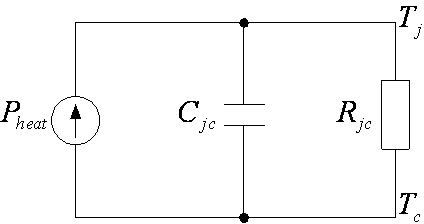
The invention discloses a novel method and a theory for extracting heat capacity and thermal time constant of a light-emitting diode (LED) system. The method comprises the following steps: 1) measuring a temperature curve of the LED junction temperature; 2) reading the corresponding time when the temperature is raised to 63.2 percent of the highest steady state temperature in the curve, and recording the time as the thermal time constant tau jc of the LED device; 3) reading the highest junction temperature and initial junction temperature in the curve, subtracting the two temperatures, dividing the thermal power input by the LED to obtain the thermal resistance Rjc of the LED device; and 4) dividing the extracted thermal resistance by the extracted thermal time constant to obtain the heat capacity Cjc of the LED device. The invention provides a simple and convenient method and theory for extracting the overall heat capacity and the overall thermal time constant of the LED device. According to the method, the thermal resistance, heat capacity and thermal time constant of the whole device can be extracted at one time, the process for extracting the thermal resistance and heat capacity of the LED device is simplified, and the process for extracting the thermal time constant of the LED device is innovatively provided.

Description

technical field [0001] The invention relates to a parameter extraction method and a set of dynamic junction temperature theoretical formulas in the design of an LED lighting system, in particular to a novel method and theoretical formula for extracting the heat capacity and thermal time constant of an LED system, belonging to the technical field of LED lighting. Background technique [0002] The prediction of thermal resistance, thermal capacity and thermal time constant of LED devices plays an important role in the prediction of device performance and the preparation of devices. Therefore, the extraction of thermal parameters of LED devices is an important topic in the field of LED lighting systems at present. Although researchers have proposed several methods, most of them have not been widely recognized due to their low prediction accuracy. At present, the most recognized and used method among many methods is the structure function method, which separates the thermal res...

Claims


Application Information

Patent Timeline
IPC IPC(8): G01N25/20
Inventor 陶雪慧张冬利
Owner SUZHOU UNIV
Learn More