Synchronous die filling mechanism of winding machine

A synchronous winding machine technology, applied in the direction of electromechanical devices, manufacturing motor generators, electrical components, etc., can solve the problems of high labor intensity, large space size of multi-strand wires, old and worn knuckles of workers, etc., to achieve winding High manufacturing efficiency, convenient winding and fully mechanized, labor-saving effect

Inactive Publication Date: 2015-02-11
SOUTHEAST UNIV
View PDF8 Cites 0 Cited by
  • Summary
  • Abstract
  • Description
  • Claims
  • Application Information

AI Technical Summary

Problems solved by technology

[0003] These two processes have been widely used in production practice, but the requirements are met at the same time: single-strand enameled wire windings, large slots, such as electric bicycle motors, each magnetic shoe of this motor is wound with a coil, and each turn of the coil It is wound by multi-strand enameled wire, and the size of the notch is very small, only about 2 mm. Due to the large space occupied by the multi-strand wire, and the problem of "twisted twist" when winding, it is impossible to use the direct winding method
The coil is tightly wound on the magnetic shoe, and the wire cannot be embedded, so the indirect winding method cannot be used.
Since there is no mechanized equipment that can satisfy the assembly of this type of motor windings, at present, only manual winding is available, which not only has high production costs and low efficiency, but also has high labor intensity, which can easily cause workers’ knuckle joints to wear out and affect their health and well-being. quality of work

Method used


Image

  • Synchronous die filling mechanism of winding machine
  • Synchronous die filling mechanism of winding machine
  • Synchronous die filling mechanism of winding machine

Examples


Embodiment Construction

[0026] The technical solution of the present invention will be described in further detail below in conjunction with the accompanying drawings.

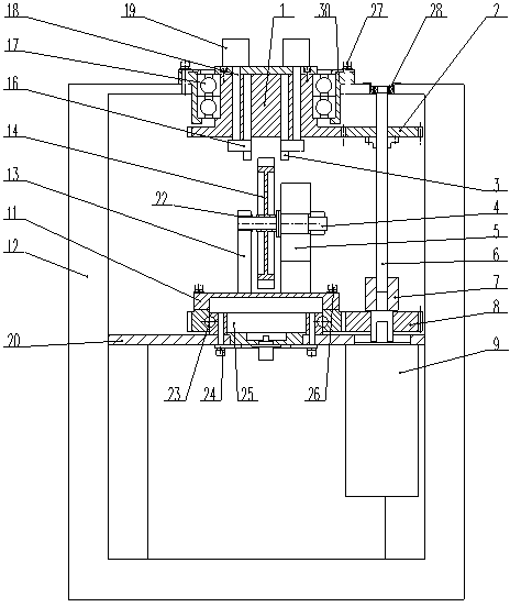
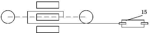
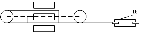
[0027] like figure 1 As shown, a synchronous mold loading mechanism of a winding machine of the present invention includes a driven gear 1, a second driving gear 2, a fixed shaft 4, a fixed shaft rotation controller 5, a synchronous shaft 6, and a first driving gear 8 , Main drive motor 9, winding turntable 11, frame 12, armature support frame 13, motor armature 14, wire arrangement mechanism 15, middle plate 20, inner turntable 25 and crimping base 30.

[0028] The middle board 20 is fixedly connected to the frame 12 . The main drive motor 9 is fixedly connected to the bottom surface of the middle plate 20 , and the output shaft of the main drive motor 9 passes through the top surface of the middle plate 20 . The output shaft of the main drive motor 9 is fixedly connected with the synchronous shaft 6 through a shaft coupling 7 . ...


PUM


Abstract

The invention discloses a synchronous die filling mechanism of a winding machine. The synchronous die filling mechanism comprises a driven gear, a second driving gear, a fixed shaft, a fixed shaft rotating controller, a synchronous shaft, a first driving gear, a main transmission motor, a winding rotating table, a frame, an armature support frame, a motor armature, a wire arranging mechanism, a middle plate, an inner rotating table and a wire press base. An output shaft of the main transmission motor is fixedly connected with the synchronous shaft, the first driving gear is fixedly connected with the output shaft of the main transmission motor, the second driving gear is fixedly connected with the synchronous shaft, a tooth space of the winding rotating table is meshed with the first driving gear, the fixed shaft is fixedly connected with the motor armature, the driven gear is connected with the wire press base and meshed with the second driving gear, the wire arranging mechanism is fixedly connected with the frame, and a wire at an outlet of the wire arranging mechanism is wound on a wire press unit. The synchronous die filling mechanism solves the problem in the prior art that a multi-strand winding small-slot motor rotor is difficult in winding.

Description

technical field [0001] The invention relates to a synchronous mold loading mechanism, in particular to a synchronous mold loading mechanism of a winding machine. Background technique [0002] The armature winding process is a crucial process link in the motor manufacturing process. There are two current motor rotor winding processes. One is the direct winding method, which uses some kind of machinery to directly wind the single-strand enameled wire in the slot of the rotor. Typical winding equipment is such as a flying fork winding machine; the other is the indirect winding method. The machine winds the enameled wire into a coil with the required number of turns, and then uses the wire embedding machine to embed the winding into the wire slot. [0003] These two processes have been widely used in production practice, but the requirements are met at the same time: single-strand enameled wire windings, large slots, such as electric bicycle motors, each magnetic shoe of this...

Claims


Application Information

Patent Timeline
Patent Type & Authority Patents(China)
IPC IPC(8): H02K15/09
Inventor 崔建伟陈杨洋宋爱国傅威杨阳
Owner SOUTHEAST UNIV
Why Eureka
Try Eureka