Field programmable gate array (FPGA) power-on reset system

A technology of electrical reset and reset signal, which is applied in the field of microelectronics, can solve the problems of dynamic switching power consumption and large short-circuit power, and achieve the effects of reducing dynamic switching power consumption and short-circuit power, reducing power dissipation, and improving safety

Active Publication Date: 2013-09-11
北京鸿智电通科技有限公司
View PDF5 Cites 10 Cited by
  • Summary
  • Abstract
  • Description
  • Claims
  • Application Information

AI Technical Summary

Problems solved by technology

[0006] The existing FPGA power-on reset starts when the chip power reaches a stable state of 2.5V. During the power-on process of the FPGA chip, the dynamic switching power consumption and short-circuit power of the chip are relatively large.

Method used


Image

  • Field programmable gate array (FPGA) power-on reset system
  • Field programmable gate array (FPGA) power-on reset system
  • Field programmable gate array (FPGA) power-on reset system

Examples


Embodiment Construction

[0022] In order to make the object, technical solution and advantages of the present invention clearer, the present invention will be further described in detail below in conjunction with the accompanying drawings.

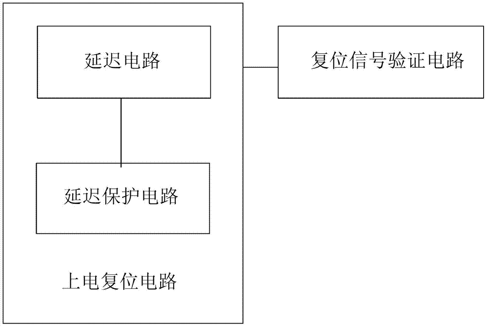
[0023] Such as figure 1 As shown, the FPGA power-on reset system disclosed by the present invention includes a power-on reset circuit for generating a POR pulse signal for power-on reset, a reset signal detection circuit for ensuring the reset validity of the POR signal, and the power-on reset The circuit is connected with the reset signal detection circuit, and the power-on reset circuit sends a POR pulse signal for power-on reset when the first power supply VDD of the chip rises to 1.6V, and the POR pulse signal is used to control the reset of the FPGA chip. The power-on reset circuit includes a delay module and a delay protection module.

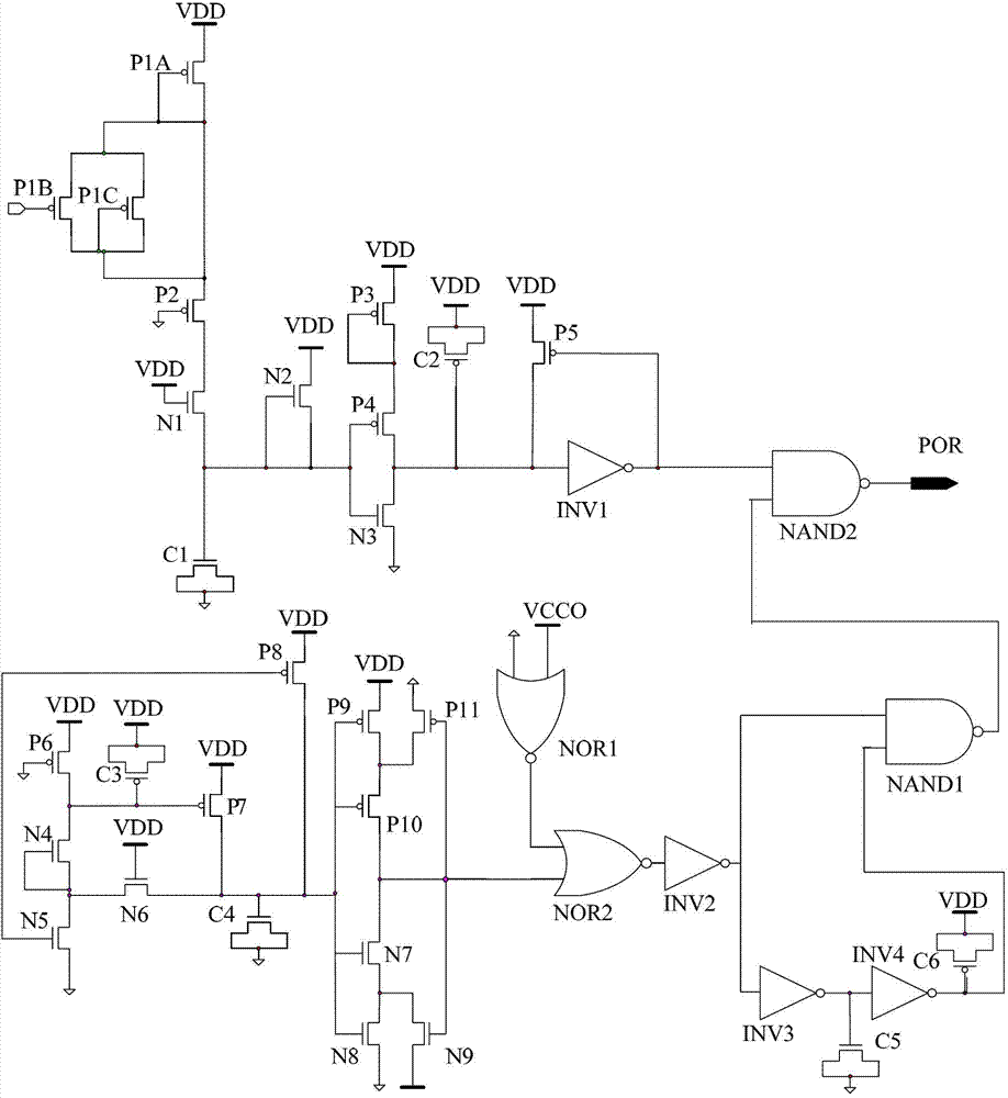
[0024] Such as figure 2As shown, the delay protection module includes PMOS transistors P1A, P1B, P1C, P2, P3, P4, P5, NM...


PUM


Abstract

The invention discloses a field programmable gate array (FPGA) power-on reset system which comprises a power-on reset circuit and a reset signal detection circuit, wherein the power-on reset circuit is used for generating power-on reset (POR) pulse signals, the reset signal detection circuit is used for ensuring reset validity of the POR signals, and the power-on reset circuit is connected with the reset signal detection circuit. The power-on reset circuit transmits the POR pulse signals when voltage drain drain (VDD) of a chip first power supply rises to 1.6V, and the POR pulse signals are used for controlling resetting of an FPGA chip. By adopting the FPGA power-on reset system, the dynamic switching loss and short circuit power of the chip are reduced in the FPGA chip power on process, and safety and starting stability of the FPGA chip are improved.

Description

technical field [0001] The invention relates to the field of microelectronics, in particular to an FPGA power-on reset system. Background technique [0002] The problem of power dissipation in integrated circuits is a thermal problem. So all problems related to heat may lead to changes in chip power consumption. But in the natural environment, heat problem is one of the most common phenomena. These problems also exist for semiconductor integrated circuits. Energy in nature is always being transformed. After the chip is powered on, a lot of electric energy has to be converted into heat energy. For relatively small chips, this converted energy will not cause fatal damage to the chip. But for large-scale chips, such as CPU, GPU, FPGA, the problem of excessive power consumption is inevitable, and the huge heat will cause serious and irreversible damage to the chip. Moreover, with the continuous advancement of semiconductor process technology and the continuous reduction of ...

Claims


Application Information

Patent Timeline
Patent Type & Authority Applications(China)
IPC IPC(8): H03K17/22
Inventor 何弢
Owner 北京鸿智电通科技有限公司
Why Eureka
Try Eureka