Vertebral artery stent

A vertebral artery and annular unit technology, applied in the field of vertebral artery stents, can solve problems such as incompatibility with the vertebral-basilar artery system, and achieve the effects of maintaining arterial patency, maintaining support strength, and good flexibility

Inactive Publication Date: 2013-09-18
苏州爱瑞德医疗科技有限公司
View PDF15 Cites 6 Cited by
  • Summary
  • Abstract
  • Description
  • Claims
  • Application Information

AI Technical Summary

Problems solved by technology

[0005] At present, there are still some problems with these intracranial stents: they are not suitable for the vertebral-basilar artery system. Based on this situation, for the vertebra-basilar artery system as an indication, it is specially suitable for restoring the blood flow state of the vertebral artery and increasing blood flow. At the same time, it has the effect of preventing plaque shedding, and it is necessary to carry out research and development and application research of new vertebral artery stents

Method used


Image

  • Vertebral artery stent
  • Vertebral artery stent
  • Vertebral artery stent

Examples


Embodiment

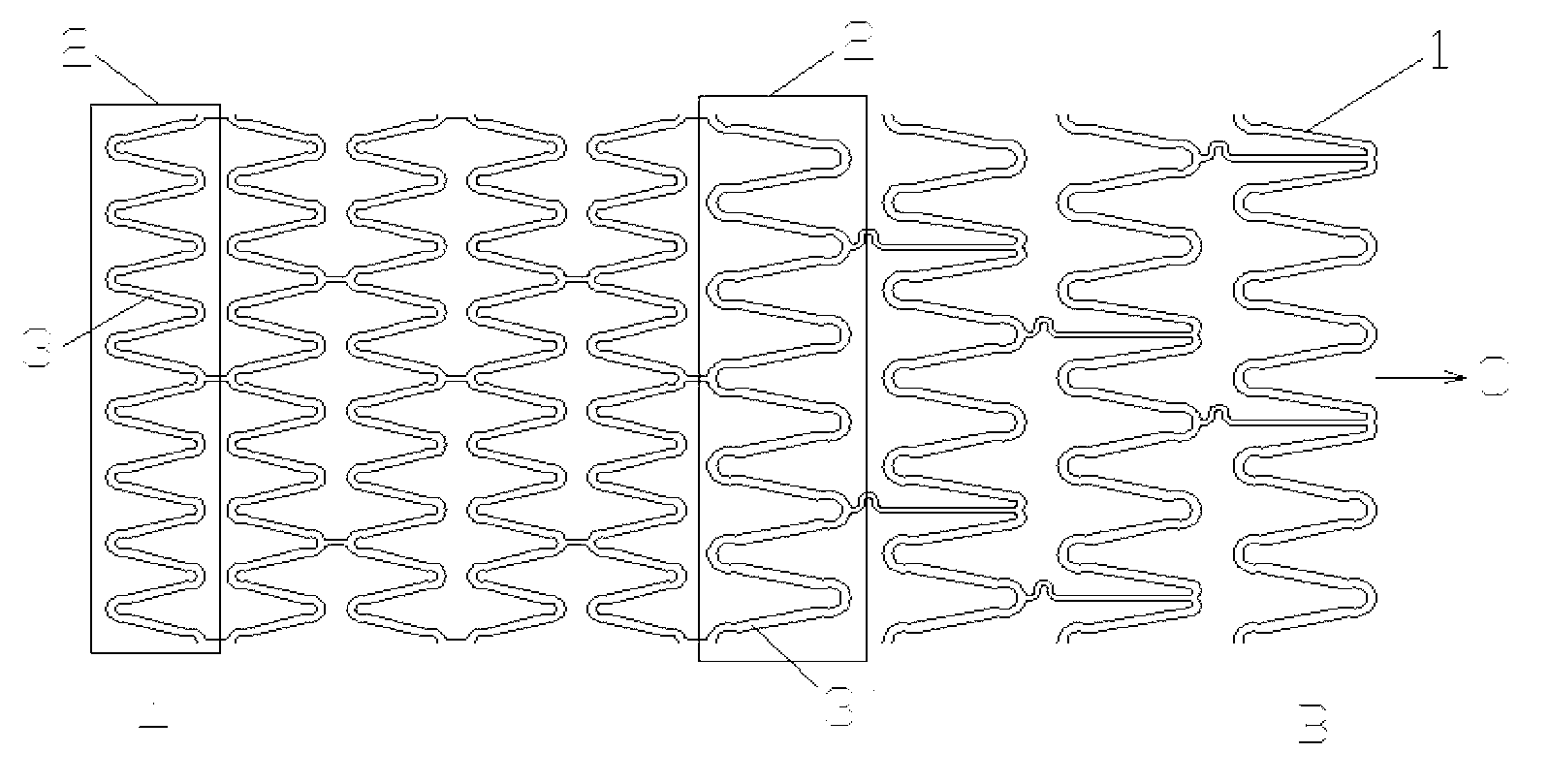
[0035] like figure 1 As shown, along the axial direction of the stent, the U-shaped structures 3 and 3' with one end open are circumferentially arranged around the central axis C of the stent 1, forming denser type-1 annular units 2 and relatively sparse type-II annular units 2' axial arrangement, U-shaped structures 2 and 2' are composed of straight line segments 4 and 4' and arc segments 5 and 5' or 6 and 6', U-shaped structures 3 and 3' are connected by connecting ribs 7 and 7' A tubular structure is formed, which can expand and deform from inside to outside.

[0036] A plurality of U-shaped structures 2 of the first type are connected in the circumferential direction to form a denser annular unit 3 of the first type; a plurality of U-shaped structures of the second type 2' are connected in the circumferential direction to form a ring-shaped unit of the second type 3' which is sparser, and, The denser one-type annular unit 3 is arranged at the proximal end of the blood...

Embodiment 1

[0074] Embodiment one: if figure 1 , figure 2 , image 3 shown.

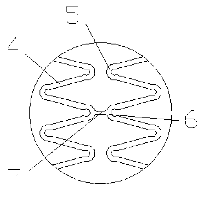
[0075] The technical solution provided by the invention is: a conical vertebral artery stent ( figure 1 ), characterized in that: the vertebral artery stent (1) includes a denser first-class annular unit (2) and a relatively sparse second-type annular unit (2′); the denser first-class annular unit (2) and the sparser second-type annular units (2′) are respectively arranged at the proximal end (A) and distal end (B) of the vertebral artery to form a tubular structure; the denser first-type annular units (2) It is composed of axially (C) symmetrical U-shaped structures (3) connected in series, and part of the U-shaped structures (3) adjacent to the corresponding circular arcs (6) are connected by short straight rods (7); The sparser second-type annular units (2') are connected in series by axial (C) asymmetric U-shaped structures (3'), and some of the U-shaped structures (3') adjacent to the correspon...

Embodiment 2

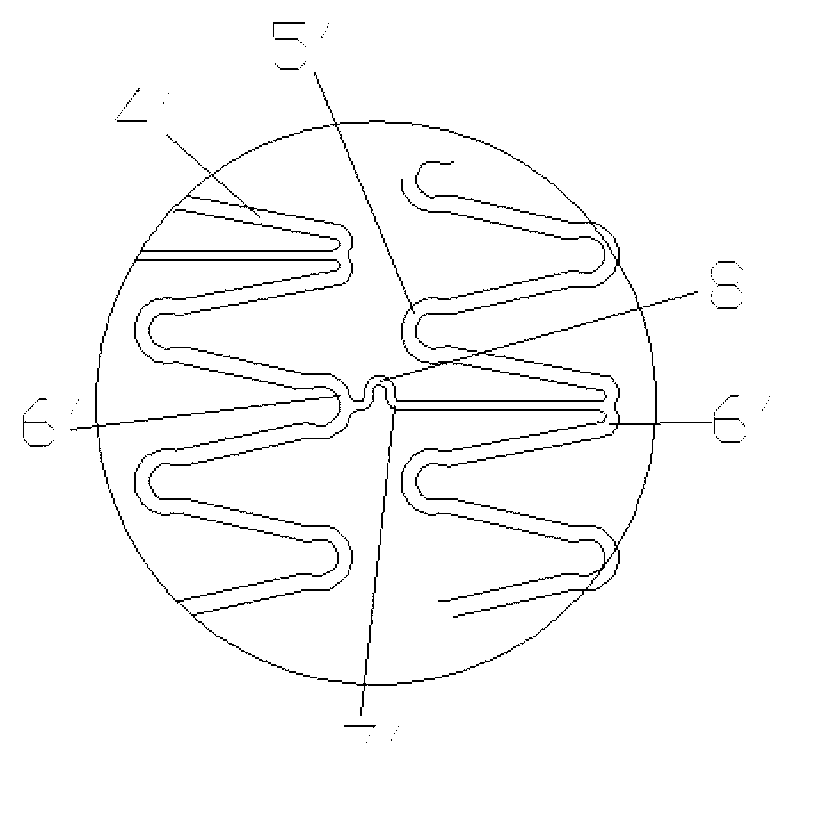
[0092] Embodiment two: if Figure 4 , Figure 5 shown.

[0093] The scaffold (1) of the present invention includes a denser type of cyclic unit (2) and a relatively sparse second type of cyclic unit (2′); the denser type of cyclic unit (2) and the described The sparser type II annular units (2′) are respectively arranged at the proximal end (A) and the distal end (B) of the vertebral artery to form a tubular structure; the denser type II annular units (2) consist of axial (C) The symmetrical U-shaped structures (3) are connected in series, and the corresponding circular arcs (6) adjacent to a part of the U-shaped structures (3) are connected by short straight rods (7); the sparser two The quasi-ring unit (2') is connected in series by axially (C) symmetrical U-shaped structures (3'), and the corresponding arcs (6') adjacent to some U-shaped structures (3') are formed by " S " shape connecting rib (7 ') links to each other.

[0094] Others are the same as in Example ...


PUM


Abstract

The invention discloses a vertebral artery stent. The vertebral artery stent comprises denser class-I annular units and sparser class-II annular units, which are connected and respectively arranged at the near end and the far end of a vertebral artery to form a tubular structure, wherein each denser class-I annular unit is formed by tandem connection of axially symmetrical U-shaped structures, and each sparser class-II annular unit is formed by tandem connection of axially asymmetrical U-shaped structures. Through the approach, the vertebral artery stent can effectively reduce the incidence of restenosis, provides a good platform for the development of vertebral artery stents, and can realize the purpose of treatment of the starting place of stenosis so as to meet the requirements on vertebral artery stenosis in clinic.

Description

technical field [0001] The invention relates to the field of medical instruments, in particular to a vertebral artery stent. Background technique [0002] Cerebrovascular disease is one of the three major diseases that cause human death. Ischemic stroke accounts for about 80% of cerebrovascular diseases, and cerebrovascular stenosis is the most important disease. Stenosis at the origin of the vertebral artery accounts for 25-40% of all cerebrovascular stenosis. Drug treatment cannot reverse the morphological changes that have been caused, and the site is not suitable for surgery due to factors such as difficult treatment techniques and high risks. Vertebral artery angioplasty and stenting (VAS) is currently a treatment option for patients with symptomatic vertebral artery stenosis who do not respond to drug therapy. Due to the limitations of drug therapy and surgical treatment, combined with the experience of extensive application of VAS in coronary atherosclerotic disease...

Claims


Application Information

Patent Timeline
Patent Type & Authority Applications(China)
IPC IPC(8): A61F2/915
Inventor 刘新峰张弢冯海全王永刚魏继昌王大伟
Owner 苏州爱瑞德医疗科技有限公司
Why Eureka
Try Eureka