
Oil-mist separator

An oil mist separator and filter technology, applied in the separation method, dispersed particle separation, dispersed particle filtration and other directions, can solve the problems of pollution and waste of the environment, and achieve the effect of reducing the use cost, protecting the environment and saving the use cost.

Inactive Publication Date: 2013-09-18
AVIC PST NANFANG GAS TURBINE COMPLETE MFG & INSTALLATION
View PDF5 Cites 5 Cited by
  • Summary
  • Abstract
  • Description
  • Claims
  • Application Information

AI Technical Summary

Problems solved by technology

[0005] The purpose of the present invention is to provide an oil mist separator to solve the technical problems that the gas turbine generating set is directly emptied through the pipeline, causing great waste and environmental pollution.

Method used


Image

  • Oil-mist separator
  • Oil-mist separator
  • Oil-mist separator

Examples


Embodiment Construction

[0035] The embodiments of the present invention will be described in detail below with reference to the accompanying drawings, but the present invention can be implemented in many different ways defined and covered by the claims.

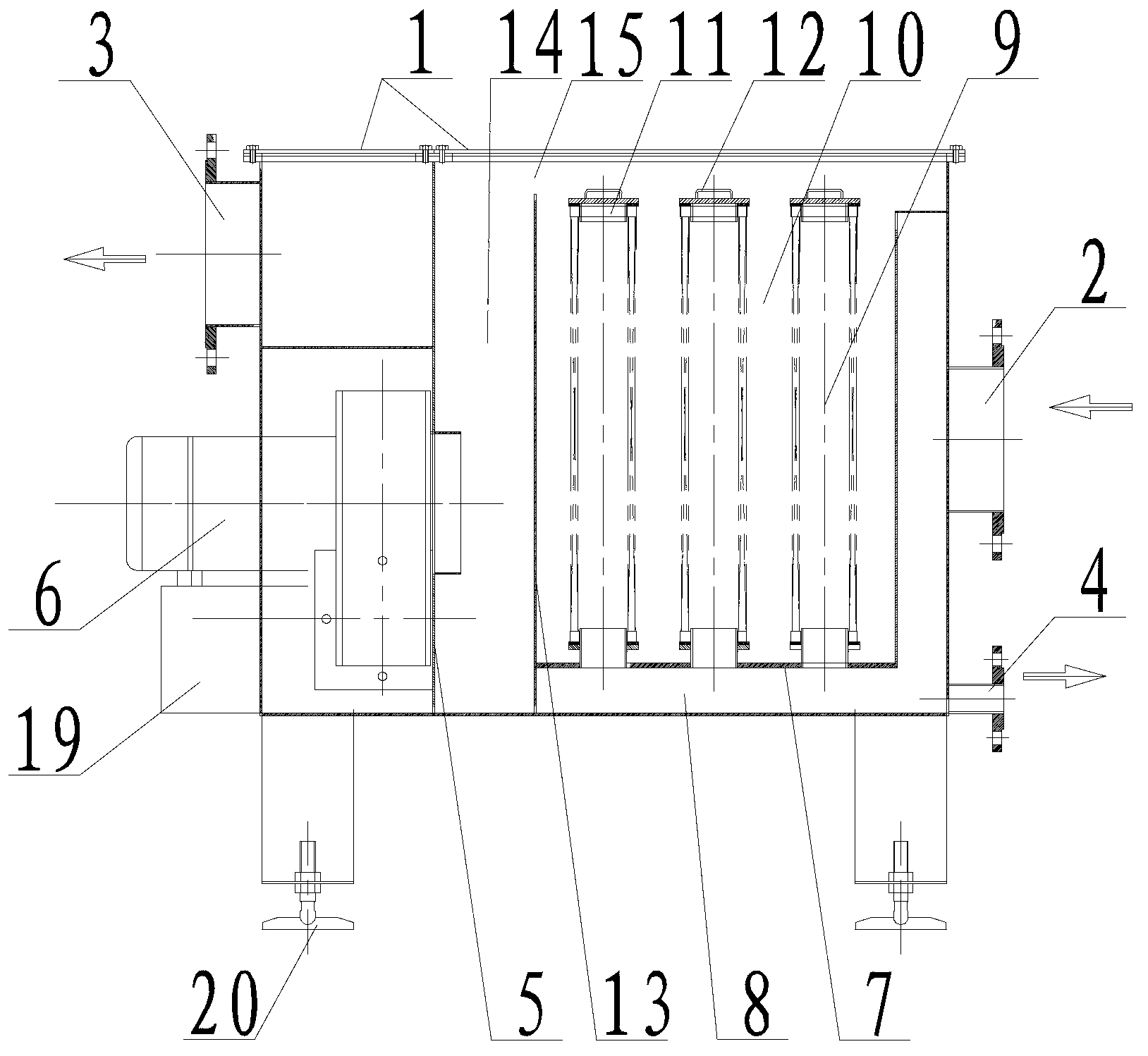
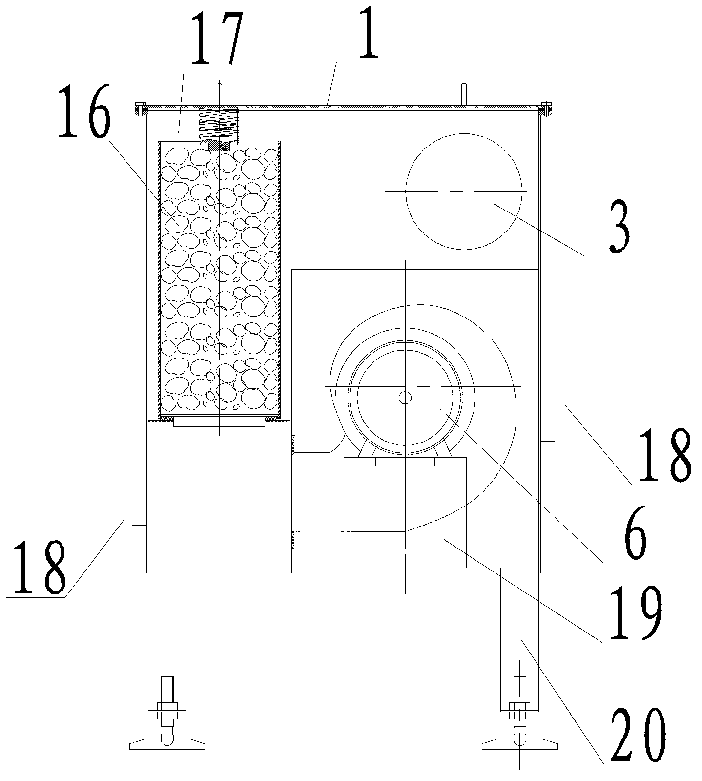
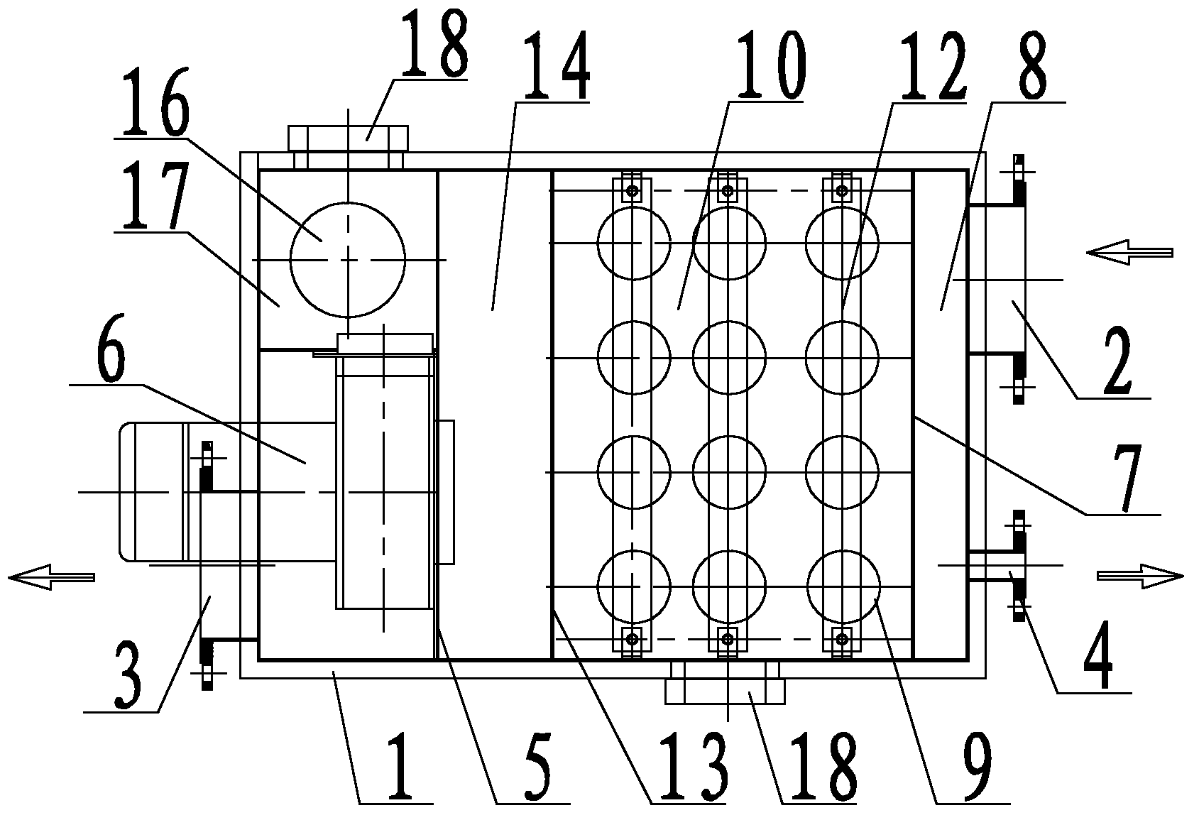
[0036] figure 1 It is a schematic diagram of the front view of the internal structure of the oil mist separator of the preferred embodiment of the present invention, figure 2 It is a schematic diagram of the left view internal structure of the oil mist separator of the preferred embodiment of the present invention, image 3 It is a schematic diagram of the top view internal structure of the oil mist separator of the preferred embodiment of the present invention, as figure 1 , 2 , 3, the oil mist separator includes a box body 1, which is provided with an air inlet 2, an air outlet port 3 and an oil outlet 4, and the box body 1 is provided with a primary filter and a secondary filter. A fully enclosed partition 5 is arranged between the filter and...


PUM


Abstract

The invention discloses an oil-mist separator which comprises a box body (1), wherein an air inlet (2), an air outlet (3) and an oil outlet (4) are formed in the box body (1); a first-stage filter and a second-stage filter are arranged in the box body (1); a full-closed partition plate (5) is arranged between the first-stage filter and the second-stage filter; the first-stage filter and the second-stage filter are communicated with each other through a fan (6) on the full-closed partition plate (5). The oil-mist separator is ingenious in structural concept, simple in structure, easy to operate, low in cost and high in interchangeability, a filter element is convenient to replace, and the production cost is greatly reduced. The difficulty of no special oil-mist separator matched with a gas turbine power generator set at present is solved. The problem that oil mist of the gas turbine power generator set is directly discharged through a pipeline and pollutes the environment is solved. Moreover, the oil mist can be well recycled, the consumption of lubricating oil is reduced, and the using cost is further reduced.

Description

technical field [0001] The invention relates to the technical field of fuel tank equipment for gas turbine generator sets, in particular to an oil mist separator. Background technique [0002] The gas turbine and generator of the gas turbine generator set are high-speed rotating equipment, and there will be friction between bearings and other equipment during operation, so lubricating oil needs to be added for lubrication. In addition to lubricating, the lubricating oil can also take away the heat generated by friction between the equipment, and the heat will enter the lubricating oil tank with the lubricating oil, so that the temperature of the oil tank will continue to increase as the operating time increases. Elevated, a large amount of oil mist will be generated in the fuel tank. If these oil mist are directly discharged into the atmosphere without treatment, one will increase the consumption of lubricating oil and increase operating costs, and the other will pollute th...

Claims


Application Information

Patent Timeline
Patent Type & Authority Applications(China)
IPC IPC(8): B01D46/00
Inventor 陈文烽彭建军徐宏
Owner AVIC PST NANFANG GAS TURBINE COMPLETE MFG & INSTALLATION
Learn More