PT (potential transformer) fuse dismounting device

A disassembler and ferrule technology, applied in the manufacture of tools, hand-held tools, etc., can solve the problems of uneven force on screws, different disassembly tools, and different diameters of insulating sleeves, etc., and achieve good results. The effect of uniform force and high installation technology

Active Publication Date: 2013-09-18
STATE GRID CORP OF CHINA +2
View PDF6 Cites 4 Cited by
  • Summary
  • Abstract
  • Description
  • Claims
  • Application Information

AI Technical Summary

Problems solved by technology

In the process of replacing the safety tube in the past, the insulating sleeve was installed vertically on the pole, and there was a spring between the end cover and the retainer, so at least two people were required to disassemble and assemble, and one person held the end cover and retainer firmly with both hands In order to keep the position between the two unchanged, another person uses a screwdriver to disassemble the bolts between the baffle and the end cover, which has the following problems: it needs more than one person to carry out; the diameter of the insulating sleeve is not the same, and different Disassembly and assembly tools; it takes about 45 to 60 minutes to replace a phase insurance; the 35kV voltage transformer structure of some substations cannot bear the weight of multiple people; the structure area of ​​some substations is small, and the staff cannot stand firmly; The insurance top cover is elastic, and it is not easy to maintain uniform strength, resulting in uneven force on the screws, resulting in poor installation technology, which may cause problems such as poor contact of the insurance, and rainwater entering the insulating sleeve.

Method used


Image

  • PT (potential transformer) fuse dismounting device
  • PT (potential transformer) fuse dismounting device

Examples


Embodiment 1

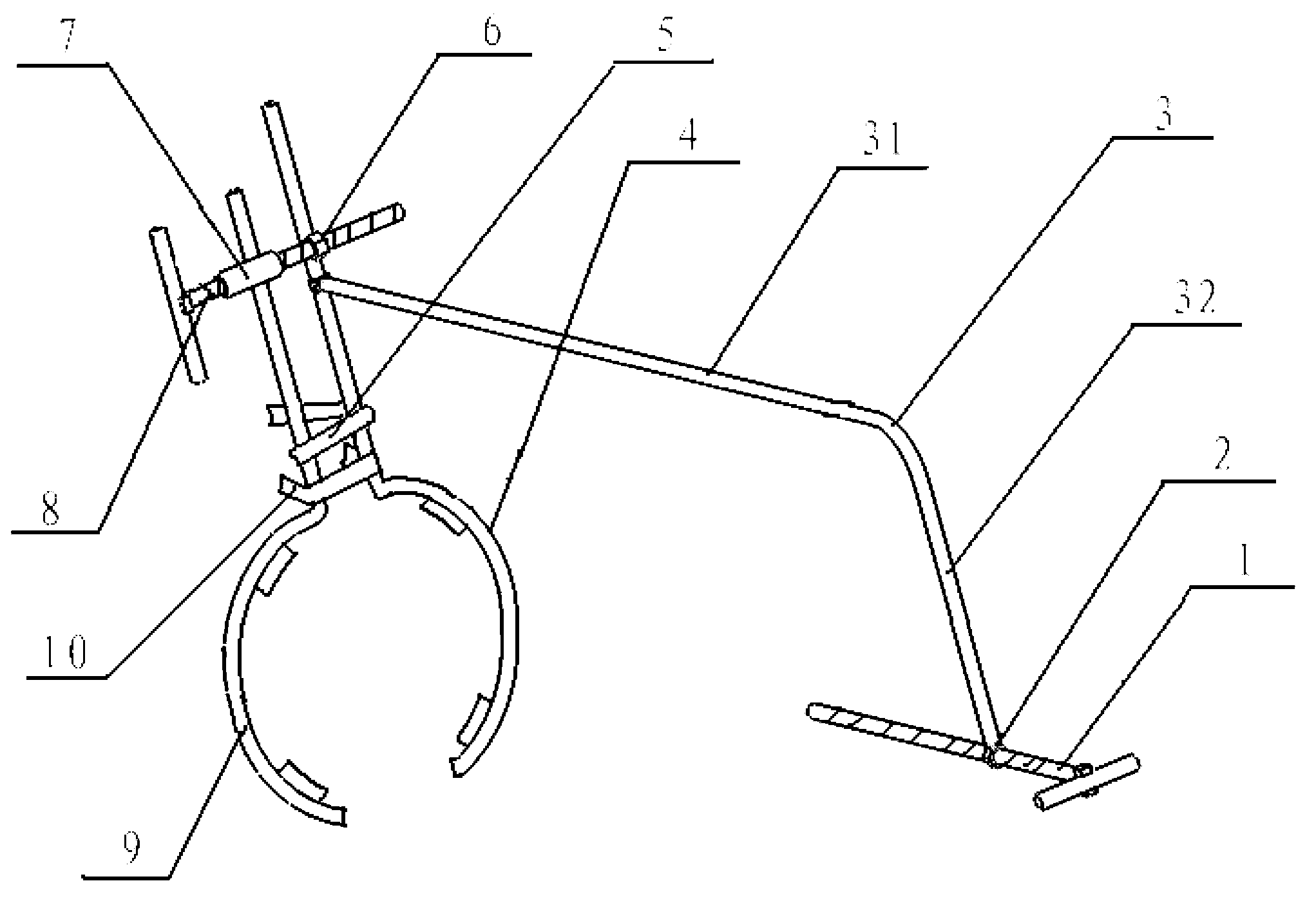
[0026] PT insurance disassembler, the structure is shown as follows figure 1 As shown, it includes a connecting frame 3 which is welded into a whole by a vertical rod 31 and a horizontal rod 32, and the horizontal rod 32 and the vertical rod 31 are perpendicular to each other. An adjustment screw 1 is provided at the outer end of the horizontal rod 32 , the adjustment screw is threadedly connected with the horizontal rod, and the adjustment screw is arranged in parallel with the vertical rod. The outer end of the adjusting screw 1 is welded with a horizontal bar handle, and the adjusting nut 2 is welded under the threaded hole of the corresponding adjusting screw on the horizontal rod. When in use, the adjusting screw 1 presses the end cover of the insulating sleeve. The lower end of the vertical rod 31 is fixedly welded with a right ferrule 4, and the right ferrule 4 corresponds to the lower part of the horizontal rod 32. The right ferrule 4 includes a connecting rod and a ri...

Embodiment 2

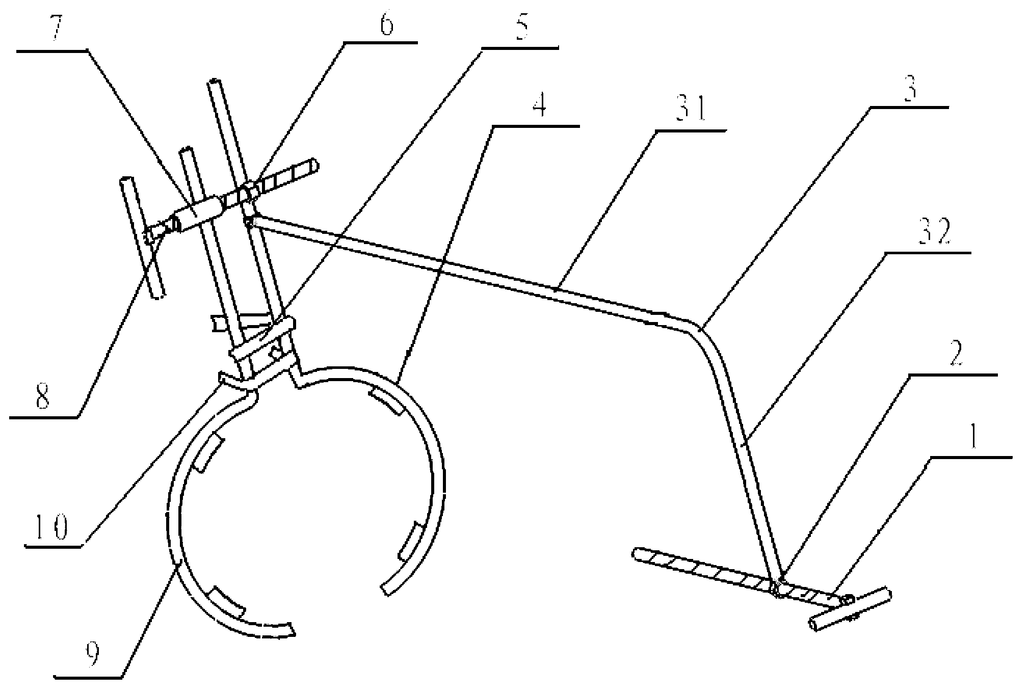
[0033] The structure of another PT fuse disassembler is shown as follows figure 2 As shown in Figure 1, the difference from Example 1 is that the left clamp and the right clamp are semi-circular arc structures that are buckled with each other to form a circle. The same, but there are only a few kinds of conventional use, so according to the size of the groove diameter of the commonly used insulating sleeve, a series of disassemblers that match the groove of the insulating sleeve and the clamp is a semi-circular arc structure can be made. Both the hoop and the sleeve are circular, and the clamp can be fully contacted and clamped with the sleeve, so the clamp with a semi-circular arc structure has a better clamping effect.


PUM


Abstract

The invention discloses a PT (potential transformer) fuse dismounting device which comprises a connecting frame formed in a way that a horizontal rod and a vertical rod vertical to each other are integrally welded, wherein the outer end of the horizontal rod is in threaded connection with an adjusting screw rod parallel to the vertical rod; a right clamping sleeve is fixedly welded in a position corresponding to the lower part of the horizontal rod at the lower end of the vertical rod; the right clamping sleeve comprises a vertical connecting rod welded at the lower end of the vertical rod and a right clamping hoop connected to the end part of the connecting rod and positioned below the horizontal rod; the right clamping hoop adopts an arc structure for clamping a groove in the pipe wall of an insulation sleeve pipe in a matched way; a left clamping sleeve is movably connected onto the right clamping sleeve; and the left clamping sleeve comprises a connecting rod parallel to that of the right clamping sleeve and a left clamping hoop which has the same radian as the right clamping hoop and adopts the arc structure. The PT fuse dismounting device has the characteristics of convenience for one-person operation, short operation time and high replacement efficiency, and is suitable for dismounting insulation sleeve pipes with different pipe diameters.

Description

technical field [0001] The invention relates to a maintenance tool in the electric power industry, in particular to a tool for disassembling and assembling a PT insurance. Background technique [0002] The inductive voltage transformer (also known as PT) is an important equipment in the substation, which uses the principle of electromagnetic induction to convert the high voltage of the main equipment of the power grid into a low voltage. In order to prevent the damage of the body and the expansion of the fault when the PT inductor coil has an internal fault, it is necessary to set a high-voltage PT insurance on the PT power supply side. PT insurance is to set an insurance tube in the inner hole of an insulating sleeve, the wall of the insulating sleeve presents a plurality of regular annular protrusions, and multiple grooves are formed between the protrusions. Springs are arranged at the conductors at both ends of the fuse tube, and end caps for pressing the springs are arr...

Claims


Application Information

Patent Timeline
Patent Type & Authority Applications(China)
IPC IPC(8): B25B27/14
Inventor 苏丛辉师威刘立强周建军刘伟良袁继森周兆辉尹翠华宋晓军
Owner STATE GRID CORP OF CHINA
Why Eureka
Try Eureka