Device for controlling flow separation caused by interference between high-Mach-number shock waves and boundary layers

A boundary layer and shock wave technology is applied in the field of devices for controlling the separation of shock waves and boundary layer interference flow, which can solve the problems of strong shock wave resistance, good eddy disturbance, and the inability of vortex generators to generate, so as to increase the resistance to The effect of reverse pressure strength, anti-interference strength enhancement, and turbulence strength enhancement

Inactive Publication Date: 2013-09-18
SHANGHAI JIAO TONG UNIV
View PDF6 Cites 10 Cited by
  • Summary
  • Abstract
  • Description
  • Claims
  • Application Information

AI Technical Summary

Problems solved by technology

But the defect of this technology compared with the present invention is: it is not suitable for hypersonic fluid, and the structure of its vortex generator can produce stronger shock wave resistance; It cannot strengthen the shear layer mixing at the trailing edge of the vortex generato

Method used


Image

  • Device for controlling flow separation caused by interference between high-Mach-number shock waves and boundary layers
  • Device for controlling flow separation caused by interference between high-Mach-number shock waves and boundary layers
  • Device for controlling flow separation caused by interference between high-Mach-number shock waves and boundary layers

Examples


Embodiment 1

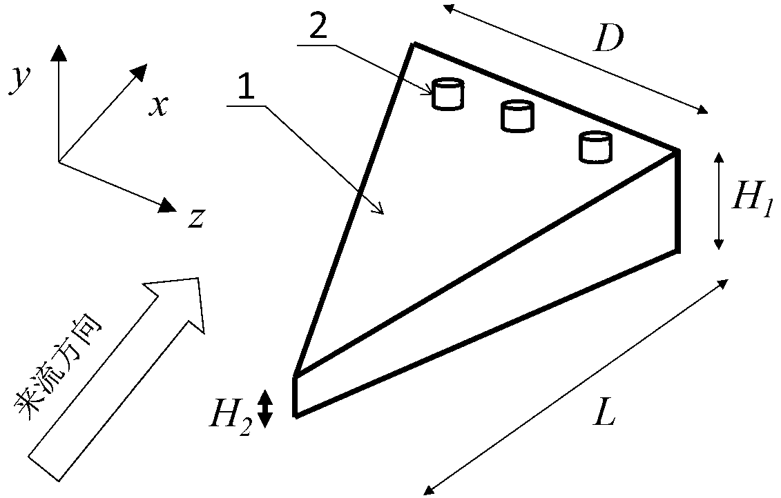
[0029] Such as figure 1 As shown, the device of this embodiment includes: a base splitter wedge 1 and a trailing edge miniature vortex generator 2, wherein: the base splitter wedge 1 of the backward wedge-shaped structure is arranged at the front end of the shock wave and the boundary layer interference zone with a distance of ( Specifically, the distance from the trailing edge of the splitter wedge to the incident point of the shock wave) is less than or equal to the thickness of three boundary layers, and the trailing edge micro-vortex generator 2 is arranged at the trailing edge of the base splitter wedge 1 .

[0030] The height H of the front and rear edges of the base splitter wedge 1 2 、H 1 And the width D and length L respectively satisfy: 0≤H 2 ≤H 1 ≤δ; 2H 1 ≤D≤5H 1 ;4H 1 ≤L≤10H 1 ; Where: δ is the thickness of the incoming flow boundary layer.

[0031] Such as figure 1 As shown, the trailing edge micro-vortex generator 2 in this embodiment adopts three vortex...

Embodiment 2

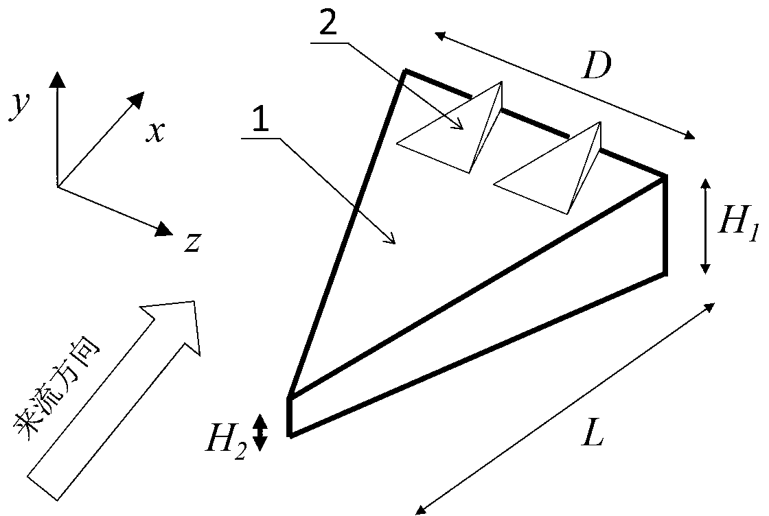
[0035] Such as figure 2 As shown, the difference between this embodiment and Embodiment 1 is that: the trailing edge miniature vortex generator 2 adopts two vortex generating units 2 axially vertical, that is, arranged in a single row along the Z-axis direction; and the vortex generation Unit 2 adopts a forward-leaning wedge structure.

[0036] The technical requirements for the shape and structure of the vortex generating unit 2 are as follows: the trailing edge height h, width d and length l of the vortex generating unit 2 respectively satisfy: 0≤h≤0.3H 1 ; h≤d≤2h; h≤l≤3h.

[0037] The control effect of this embodiment under the condition of high Mach number is similar to that of Embodiment 1.

Embodiment 3

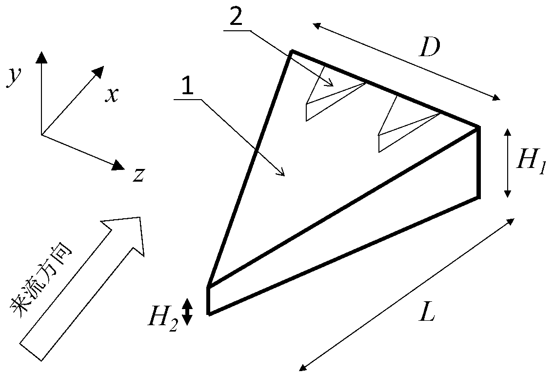
[0039] Such as image 3 As shown, the difference between this embodiment and Embodiment 1 is that: the trailing edge miniature vortex generator 2 adopts two vortex generating units 2 axially vertical, that is, arranged in a single row along the Z-axis direction; and the vortex generation Unit 2 adopts a reclining wedge structure.

[0040] The technical requirements for the shape and structure of the vortex generating unit 2 are as follows: the front edge height h, width d and length l of the vortex generating unit 2 respectively satisfy: 0≤h≤0.3H 1 ; h≤d≤2h; h≤l≤3h.

[0041] The control effect of this embodiment under the condition of high Mach number is similar to that of Embodiment 1.


PUM


Abstract

The invention discloses a device for controlling flow separation caused by interference between high-Mach-number shock waves and boundary layers in the technical field of hypersonic flight vehicles. The device comprises a base flow-dividing wedge and a miniature trailing edge vortex generator, wherein the base flow-dividing wedge in a lean-back wedged structure is arranged at the front end of a shock wave and boundary layer interference region, and the distance, in particular the distance between a trailing edge and a shock wave incidence point, is smaller than or equal to the thickness of three boundary layers; the miniature trailing edge vortex generator is arranged on the upper surface of the trailing edge of the base flow-dividing wedge. According to the device, a dropping vortex structure can be generated on the side edge of the flow-dividing wedge to take away a low-energy fluid of the interference region, and a high-turbulivity shearing layer on the trailing edge serves as a buffer strip. The device can control the flow separation caused by the interference between the shock waves and the boundary layers, realizes separation flow control under the condition of Mach number of 4 to 10, and has the characteristics of simple structure, stable performance and the like.

Description

technical field [0001] The invention relates to a device for separating the control shock wave from the boundary layer interference flow in the technical field of hypersonic aircraft, specifically a split-flow control high Mach number shock wave and auxiliary flow generator with a composite vortex generator. A device in which the surface interferes with flow separation. Background technique [0002] Hypersonic aircraft is one of the strategic equipment to achieve rapid military strikes and quick responses. In recent years, it has attracted the attention of researchers at home and abroad. Shock wave and boundary layer interference widely exist in the internal and external flow of hypersonic aircraft. When the aircraft flies at a high Mach number, strong shock wave and boundary layer interference often lead to the separation of large-scale flow in the boundary layer, accompanied by Strong additional resistance and total pressure loss. At the same time, the turbulence intensit...

Claims


Application Information

Patent Timeline
IPC IPC(8): B64C23/06
CPCY02T50/10
Inventor 李伟鹏
Owner SHANGHAI JIAO TONG UNIV
Why Eureka
Try Eureka