Single-wheel cycled multi-car elevator

A multi-car and car technology, applied in the field of multi-car elevators, can solve the problems of low operation efficiency, car overturning, not considering the problem of track turnout, etc. The effect of shortening the waiting time

Inactive Publication Date: 2013-09-18
HENAN POLYTECHNIC UNIV
View PDF7 Cites 13 Cited by
  • Summary
  • Abstract
  • Description
  • Claims
  • Application Information

AI Technical Summary

Problems solved by technology

However, for this kind of multi-car elevator and its circulation system, the conversion mechanism needs to remove the car and its corresponding track when the car circulates and avoids. There is a discontinuity in the running track of the car, and the conversion mechanism needs a large driving force. , cycle avoidance process is complex and other issues
In addition, the utility model with the patent number "CN201020659140.7" discloses "a circular multi-car elevator", which proposes a multi-car elevator that can realize the circulation of multiple cars in a circular track, but there are When the car circulates from one hoistway to another, the car has the problem of overturning; at the same time, this multi-car elevator does not consider the problem of the track switch, and the car can only run in a closed cycle, and the operating efficiency is not high. limited

Method used


Image

  • Single-wheel cycled multi-car elevator
  • Single-wheel cycled multi-car elevator
  • Single-wheel cycled multi-car elevator

Examples


Embodiment 1

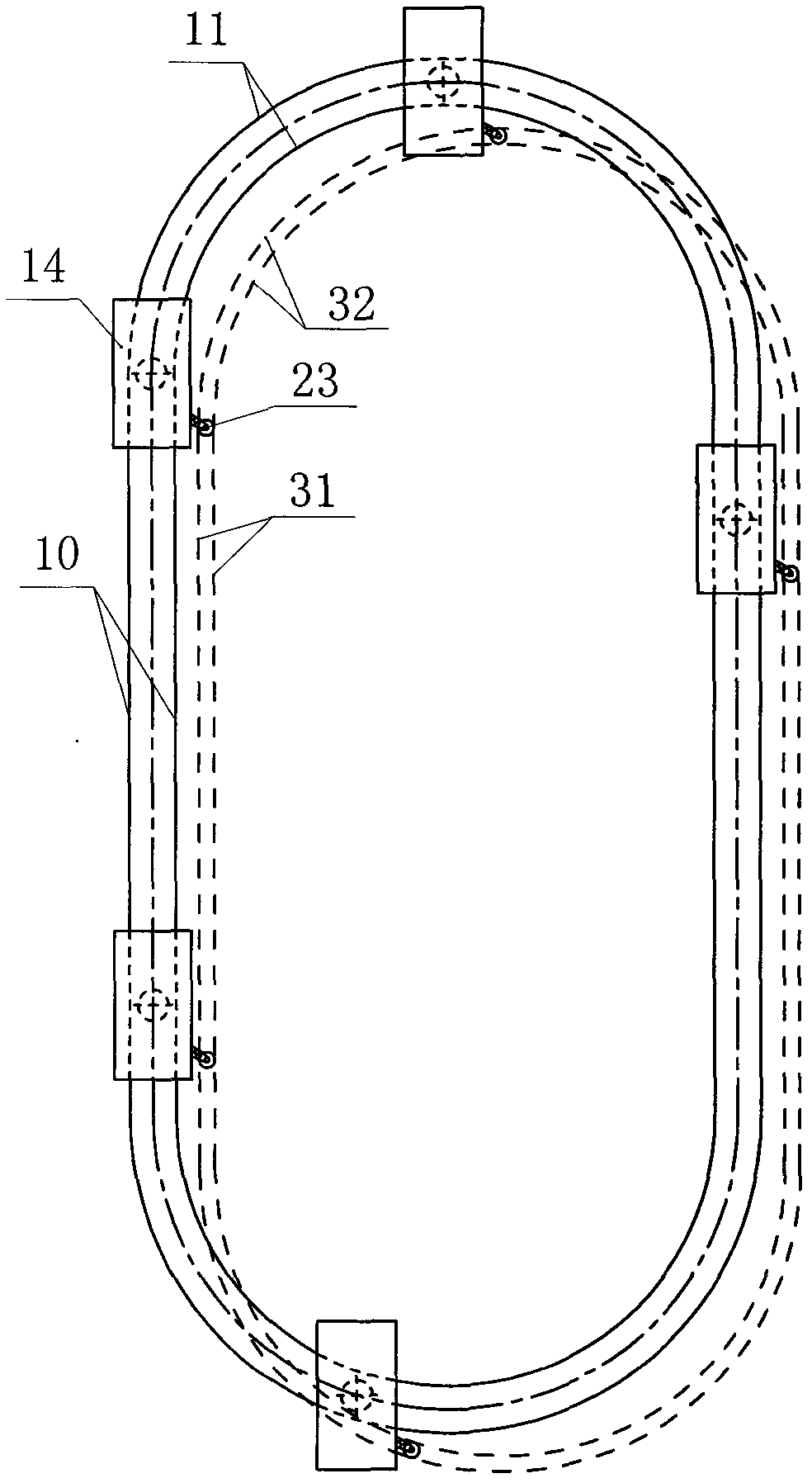
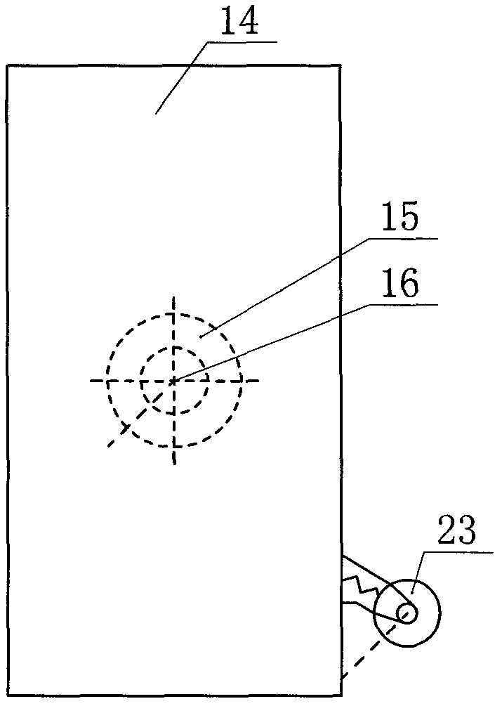
[0021] Such as Figure 1~3 As shown, a circular multi-car elevator includes a car 14, a drive mechanism, and a car positioning rail. The car 14 is provided with a car wheel 23, and the car wheel 23 is arranged in the car wheel positioning rail. , the car wheel positioning rail comprises a vertical section 31 of the car wheel positioning rail and a curved section 32 of the car wheel positioning rail. It includes a car positioning rail vertical section 10 and a car positioning rail curved section 11.

[0022] In this embodiment, the vertical section 10 of the car positioning rail and the curved section 11 of the car positioning rail form a circular closed car positioning rail, and the driving mechanism drives the car 14 to move along the car positioning rail, and the car Wheel 23 runs along the car wheel alignment rail all the time, can guarantee that car can not overturn in running process. In addition, several cars can exist in the car positioning rail at the same time, ther...

Embodiment 2

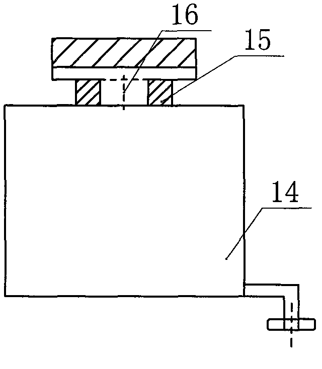
[0024] Such as Figure 4~7 As shown, the driving mechanism includes a driving power source and driving car I 35a, driving car II 35b, driving car III 35C, between driving car I 35a and driving car II 35b, between driving car II 35b and driving car III 35C Connected by a ball chain device 37, the car 14 is connected with the driving trolley II 35b through the connecting shaft 16 and the turntable 15, and the driving trolley II 35b is provided with a brake 38. The brake 38 is arranged on both sides of the driving trolley 35b, and uses the top surface of the car positioning rail as the braking surface to realize the braking of the car 14. A primary armature 34b is provided on each driving trolley. When the winding in the primary armature 34b is energized, a traveling magnetic field is formed, which interacts with the permanent magnetic field generated by the permanent magnet 34a to generate lifting force and drive the car 14 to run.

[0025] Wherein, the driving power source inc...

Embodiment 3

[0029] Such as Figure 8-9 As shown, two sets of primary armatures 34b are arranged on the connecting plate 41 of the positioning wheel group, two sets of permanent magnets 34a are arranged on the fixed part of the power source, brake rails 43 are arranged between the two sets of permanent magnets 34a, and the brake 38 is arranged on on the brake rail 43. Other structures are with embodiment 2.


PUM


Abstract

The invention discloses a single-wheel cycled multi-car elevator comprises cars, a driving mechanism and car positioning rails, wherein each car is provided with a car wheel; the car wheels are arranged inside car wheel positioning rails; each car wheel positioning rail comprises car wheel positioning rail vertical sections and car wheel positioning rail curved passage sections; each car is connected with the driving mechanism through a rotary disk and a connecting shaft; and each car positioning rail comprises car positioning rail vertical sections and car positioning rail curved passage sections. According to the single-wheel cycled multi-car elevator, the driving mechanism drives the cars to move along the car positioning rails, while the car wheels always run along the car wheel positioning rails so as to ensure that the cars cannot turn over during the running process; and the rails are continuous, so that the cycle of the cars is relatively simple. A plurality of cars can exist inside the car positioning rails simultaneously, so that the well space utilization rate of the elevator is improved, the elevator waiting time is shortened, the transport capacity is increased, and the single-wheel cycled multi-car elevator is particularly suitable for being used in high-rise buildings.

Description

technical field [0001] The invention relates to a circular elevator, in particular to a multi-car elevator. Background technique [0002] In traditional sheave traction hoistway elevators, only one car can run in each hoistway. Elevators with this structure are more practical in low-rise buildings, but for more and more high-rise buildings in modern cities, there are problems such as small number of cars, low transportation capacity, and long waiting time. use. The existing solution is to install more single-car elevators by increasing the number of elevator shafts, and double-deck car elevators using traditional sheave traction technology, which improves the transportation capacity to a certain extent and shortens the waiting time for elevators, but A large number of elevator shafts have taken up a lot of valuable building space and building costs, and have not fundamentally solved the problem. For high-rise and ultra-high-rise buildings with many people and heavy loads,...

Claims


Application Information

Patent Timeline
Patent Type & Authority Applications(China)
IPC IPC(8): B66B9/00B66B11/04B66B7/02
Inventor 汪旭东许宝宝朱军封海潮许孝卓高彩霞王新掌袁世鹰
Owner HENAN POLYTECHNIC UNIV
Why Eureka
Try Eureka