Slab end isolation mounting device for floating track bed

A floating road and vibration isolation technology, applied in the direction of roads, tracks, ballast layers, etc., can solve the problem that the horizontal position and stability requirements of floating slabs cannot be met, and the prefabricated long slabs are difficult to adapt to changeable curve elements, The problem of large sinking of floating slabs can achieve the effects of convenient transportation and hoisting, easy guarantee of product quality, and shortened production cycle

Active Publication Date: 2013-09-18
GERB QINGDAO VIBRATION CONTROL +1
View PDF8 Cites 25 Cited by
  • Summary
  • Abstract
  • Description
  • Claims
  • Application Information

AI Technical Summary

Problems solved by technology

However, a traditional floating slab with a length of 25m weighs more than 70 tons. The carrying capacity of the hoisting and transporting tools in the existing tunnel is only 10 tons. The difference is too large, and the overall prefabrication cannot be transported; In curved areas, it is difficult for prefabricated long slabs to adapt to changing curve elements, so prefabricated slab technology has not been able to be applied in the construction of multi-point supported floating track bed projects such as steel spring floating slabs
In theory, although there is a feasible solution to change long floating slabs to short floating slabs, changing long slabs to short slabs will bring a series of problems in dynamics, safe...

Method used


Image

  • Slab end isolation mounting device for floating track bed
  • Slab end isolation mounting device for floating track bed
  • Slab end isolation mounting device for floating track bed

Examples


Embodiment 1

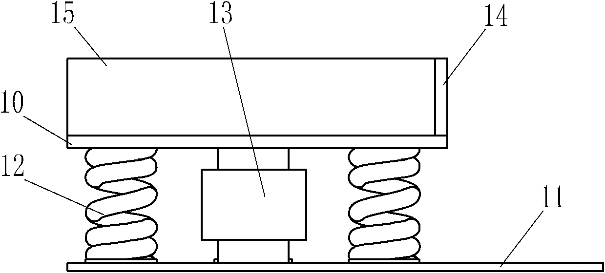
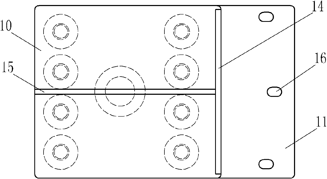
[0075] Such as figure 1 and figure 2 The vibration isolation device at the end of the floating track bed of the present invention includes a top plate 10, a bottom plate 11, an elastic element 12 and a damping element 13. The elastic element 12 and the damping element 13 are arranged between the top plate 10 and the bottom plate 11. In this example, the elastic element 12 is specifically eight helical steel springs, and the damping element 13 is specifically a small-hole throttling damper, and the elastic element 12 and the damping element 13 are arranged symmetrically along the transverse middle section of the vibration isolation device at the end of the floating track bed. In addition, a plate end horizontal limit device is also provided on the top plate 10, and the plate end horizontal limit device is composed of a plate end transverse limit device and a plate end longitudinal limit device. Wherein, the plate end lateral limiting device is a transverse limiting protrusion...

Embodiment 2

[0083] Such as Figure 8 and Figure 9 The difference between the floating bed end vibration isolation device of the present invention and the first embodiment is that the floating road bed end vibration isolation device is provided with two sets of plate end longitudinal limit devices, and each set of plate end longitudinal limit devices consists of longitudinal A limiting plate 33 , an adjusting bolt 35 and a locking nut 34 are formed. The adjusting bolt 35 is set through a supporting plate 36 , and the supporting plate 36 is welded and fixed together with the lateral limiting protrusion 14 and the top plate 10 .

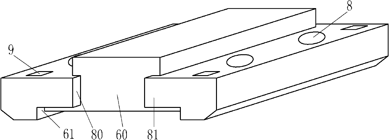
[0084] Such as Figure 11 Prefabricated short panels shown, with image 3 The difference between the prefabricated short slabs shown is that each prefabricated short slab is provided with four placement grooves 27 that cooperate with elastic vibration isolators, and in addition, two mid-mounted shear hinges are symmetrically arranged on the end faces of the pref...

Embodiment 3

[0089] Based on the technical principle described in Embodiment 2, such as Figure 14 and Figure 15 The difference between the floating bed end vibration isolation device of the present invention and the second embodiment is that in this example, the floating road bed end vibration isolation device is provided with two sets of longitudinal limit plates 33, adjusting bolts 35 and In addition to the plate end longitudinal limiting device formed by the locking nut 34, two groups of plate end transverse limiting devices composed of the transverse limiting plate 40, the adjusting bolt 42 and the locking nut 41 are also provided, wherein the plate end lateral limiting The adjusting bolt 42 in the device is set through the support plate 43, and the support plate 43 is welded and fixedly connected with the top plate 10 and the support plate 36 respectively.

[0090] Apply the vibration isolation device at the end of the floating track bed of the present invention described in this e...


PUM


Abstract

The invention belongs to the field of vibration control and relates to a slab end isolation mounting device for supporting a floating slab in a floating track bed. The slab end isolation mounting device comprises a top slab, a bottom slab, an elastic element and a damping element, wherein the elastic element and the damping element are arranged between the top slab and the bottom slab. The slab end isolation mounting device is characterized in that the top slab is provided with a slab end horizontal limiting device; the slab end horizontal limiting device comprises a slab end transverse limiting device or/and a slab end lengthwise limiting device. The slab end isolation mounting device and a prefabricated short slab in the length of 1.2-8m form the structure of the floating track bed together, the prefabricated production and lifting construction of the floating slab are possible, and the prefabricated short slab is limited lengthwise and transversely through the slab end horizontal limiting device, so that the stability and safety of the structure of the floating track bed in the travelling process are guaranteed, the construction speed is greatly improved, the construction period is further shortened, the construction difficulty is reduced, and the production cost is saved. The isolation mounting device is high in practicability, safe, reliable and high in cost performance and has a wide market application prospect.

Description

technical field [0001] The invention belongs to the field of vibration control, and relates to a vibration isolation device for a railway floating track bed, in particular to a plate end vibration isolation device for supporting a floating plate in the floating track bed. Background technique [0002] Vibration and noise are recognized as the most widely affected public hazards, and they are also a problem that needs to be solved urgently in the development of rail transit in recent years. Among the existing rail transit vibration and noise reduction technologies, the most successful practical application is the component floating technology, typically the floating ballast bed technology, which has high vibration isolation efficiency and stable working performance, which has become a consensus in the industry, such as patent No. The Chinese patent ZL200410035441.1 discloses a typical built-in floating ballast bed structure and a corresponding vibration isolation device. How...

Claims


Application Information

Patent Timeline
IPC IPC(8): E01B1/00E01B19/00
Inventor 白廷辉毕湘利尹学军宋键刘加华平轶王建立刘扬黄俊飞董国宪范利辉孔祥斐薛松王乾安
Owner GERB QINGDAO VIBRATION CONTROL
Why Eureka
Try Eureka