
Dynamic compactor boom and dynamic compactor

A technology of dynamic tamping machine and jib, which is applied in the fields of soil protection, construction, infrastructure engineering, etc. It can solve the problems of complex processing and manufacturing, installation and disassembly, etc., and achieve good manufacturability, reduced lifting height, and material saving. Effect

Active Publication Date: 2013-09-18
XCMG CONSTR MACHINERY
View PDF5 Cites 7 Cited by
  • Summary
  • Abstract
  • Description
  • Claims
  • Application Information

AI Technical Summary

Problems solved by technology

However, since the main structure of the boom adopts flange connection, the processing, manufacturing, installation and disassembly of the boom are relatively complicated.

Method used


Image

  • Dynamic compactor boom and dynamic compactor
  • Dynamic compactor boom and dynamic compactor
  • Dynamic compactor boom and dynamic compactor

Examples


Embodiment Construction

[0034] The technical solutions of the present invention will be described in further detail below with reference to the accompanying drawings and embodiments.

[0035] In describing the present invention, it is to be understood that the terms "central", "longitudinal", "transverse", "front", "rear", "left", "right", "vertical", "horizontal", The orientations or positional relationships indicated by "top", "bottom", "inner", "outer", etc. are based on the orientations or positional relationships shown in the drawings, and are only for the convenience of describing the present invention and simplifying the description, rather than indicating or implying the Means that a device or element must have a specific orientation, be constructed and operate in a specific orientation, and therefore should not be construed as limiting the scope of the invention.

[0036] In the dynamic compaction operation, in the process of pulling out the hammer and lifting the boom, the bending moment on...


PUM


Abstract

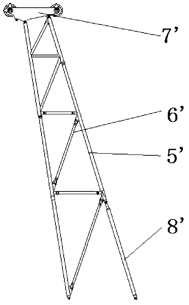
The invention relates to a dynamic compactor boom and a dynamic compactor. The dynamic compactor boom comprises a bottom knuckle arm, a plurality of middle knuckle arms and a top knuckle arm, wherein the bottom knuckle arm, the middle knuckle arms and the top knuckle arm are sequentially connected in series and are respectively knuckle arms with a trussed structure mainly composed of an upper main chord member, a lower main chord member, a diagonal web member and a transverse connecting rod, and the knuckle arms are connected with each other through pin shafts; the cross section area of the dynamic compactor boom is homogeneously and linearly increased from the top knuckle arm to the bottom knuckle arm. The vibration and fatigue problems of large-energy-level dynamic compactors of the prior art can be improved, and meanwhile the processing technology and the disassembly and assembly problem of the boom can be considered.

Description

technical field [0001] The invention relates to the field of engineering machinery, in particular to a dynamic compaction machine arm frame and a dynamic compaction machine provided with the dynamic compaction machine arm frame. Background technique [0002] With the acceleration of urbanization in our country, a large number of land reclamation and land reclamation projects have been carried out, and the collapsible loess area and soft clay area are widely distributed in our country, so the dynamic compaction construction machinery will develop into large-scale and serialized . The arm frame is the key operating part of the dynamic compaction machine, and the rammer is lifted and unloaded by the arm frame to realize the compaction of the foundation. The booms of existing crawler-type dynamic compaction machines are mostly born out of the booms of crawler cranes. With the development of the dynamic tamping machine, a series of problems such as boom design, production, inst...

Claims


Application Information

Patent Timeline
Patent Type & Authority Applications(China)
IPC IPC(8): E02D3/046
Inventor 李利斌周海涛赵波
Owner XCMG CONSTR MACHINERY
Learn More