
Moving point array solar focusing thermal power generation system

A thermal power generation system and solar technology, applied in the field of solar energy utilization, can solve the problems of low solar energy collection efficiency, inability to adapt to needs, and large scale, and achieve the effects of overcoming low solar energy collection time, improving utilization time and efficiency, and improving tracking efficiency

Inactive Publication Date: 2013-09-18
CHENGDU AONENGPU TECH
View PDF5 Cites 0 Cited by
  • Summary
  • Abstract
  • Description
  • Claims
  • Application Information

AI Technical Summary

Problems solved by technology

[0004] The tower system is a solar photothermal conversion device that uses a solar mirror as a heliostat and focuses multiple solar reflectors on a solar photothermal conversion device. The utilization time of the solar mirror is only 4-6 hours. For example, the solar mirror on the east side of the tower is basically unusable in the morning and can only be used after noon or afternoon, so the efficiency of solar energy collection is low. This technical solution can realize high-temperature collection , but usually its size is large, not suitable for small or home systems
[0005] In 2006100203529 Solar Optical Mirror Tracking Utilizer and Its Array, the inventor disclosed zoom tracking systems with cross-shaped and disk-shaped structures, but this structure should belong to a combination of one or a group of solar mirrors and a solar photothermal conversion device At the same time, it is still limited to the cross-shaped and disc-shaped structures and cannot meet more needs

Method used


Image

  • Moving point array solar focusing thermal power generation system
  • Moving point array solar focusing thermal power generation system
  • Moving point array solar focusing thermal power generation system

Examples


Embodiment 1

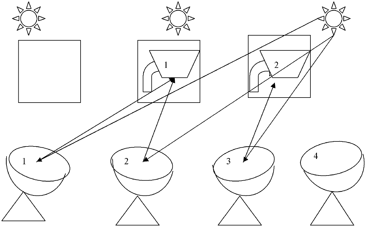
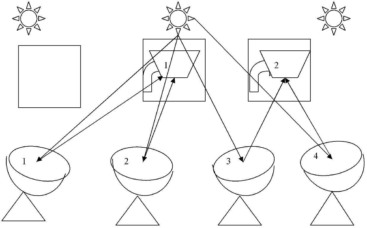
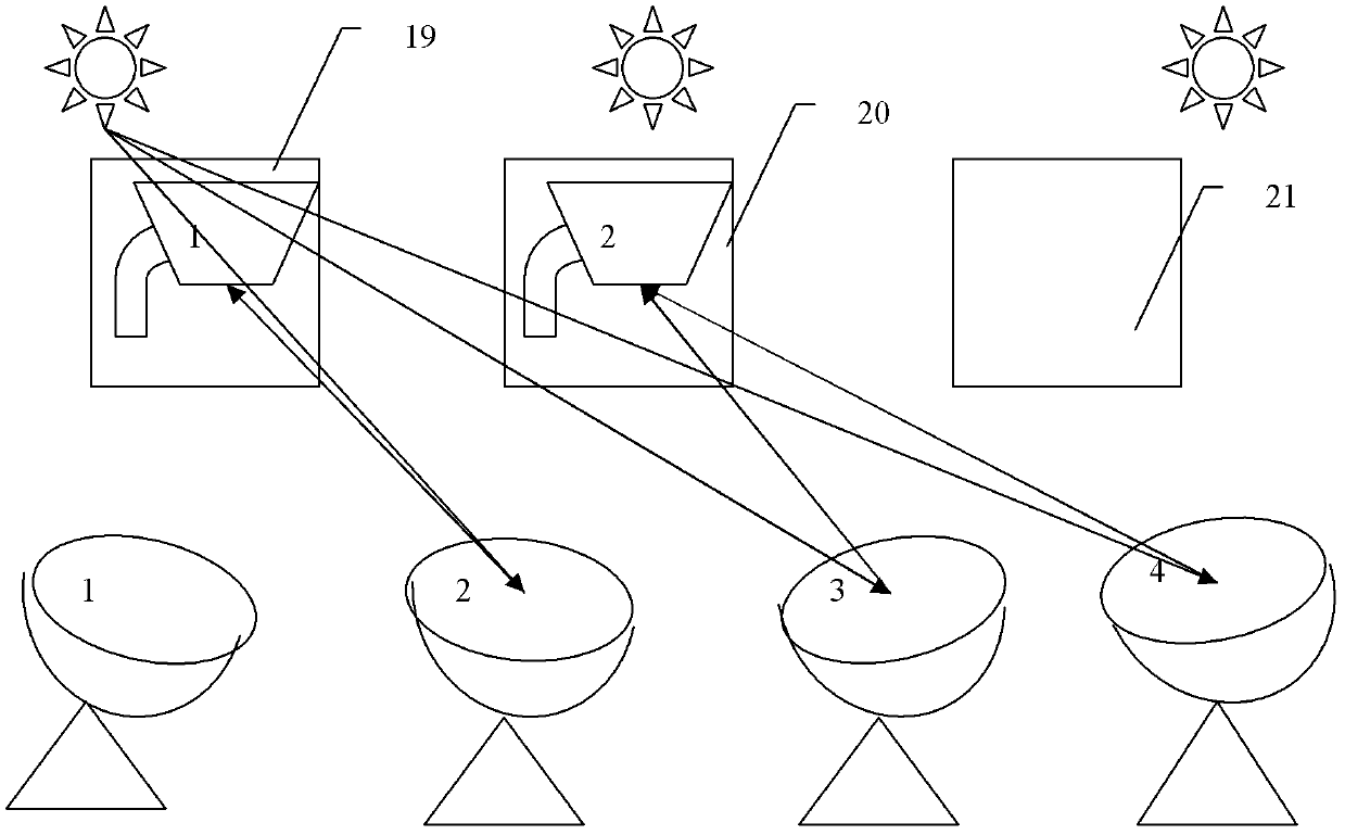
[0069] Embodiment 1: A mobile point array solar energy collection and utilization system composed of 4 solar mirrors and 2 solar energy utilization devices

[0070] as attached figure 1 , 2 , 3 shows the moving point array solar collection and utilization system composed of 4 solar mirrors and 2 solar photothermal conversion devices, figure 1 , 2 , 3 are the collection and utilization of solar energy in the morning, noon and afternoon respectively, figure 1 In the morning, the sun rises from the east, solar mirrors No. 1, 2 and No. 3 focus the solar energy on No. 1 and No. 2 solar photothermal conversion devices respectively, realizing the tracking and focusing of solar energy; figure 2 At noon, the sun is located in the central area of ​​the sky, No. 1 and No. 2 solar mirrors respectively focus the solar energy on the No. 1 solar photothermal conversion device, No. 3 and No. 4 solar mirrors focus on the No. 2 solar storage device to realize the tracking and focusing of so...

Embodiment 2

[0071] Embodiment 2: A moving point array solar energy collection and utilization system composed of 12 solar mirrors and 6 solar energy utilization devices

[0072] This example Figure 4 The mobile point array solar collection and utilization system consisting of 12 solar mirrors and 6 solar photothermal conversion devices is shown. The array of columns is arranged, and the solar photothermal conversion device is respectively arranged in the middle area of ​​the three rows of solar mirrors.

[0073] In the different time periods of morning, noon, and afternoon, solar mirrors 1-12 can choose different solar photothermal conversion devices from 1-6 to focus, and select different focus points to focus according to the actual solar energy collection efficiency. For solar mirrors 1-12 at different positions, the choice of focusing solar photothermal conversion devices is also different. For solar mirrors 1, 5, 9, 4, 8, and 12 on both sides, there can be 2 solar mirrors The photot...

Embodiment 3

[0076] Embodiment 3: 1*3 moving point solar energy tracking utilization system

[0077] as attached Figure 5 As shown, this embodiment adopts three parabolic dish solar mirrors (2), which are arranged on a parabolic connecting part, and each solar mirror is connected to the parabolic connecting part through a system axis, and the horizontal axis of the system axis The axis and the longitudinal axis are perpendicular to each other. This embodiment is a solar mirror bracket composed of three system axes arranged on the connecting parts. The connecting parts do not move, but the three system axes move. connection, set physical and optical sensors on each solar mirror (2), the solar tracking control device is an integrated electronic control device composed of motor, transmission gear and electronic control part, and adopts a tracking system that complements physical and optical tracking to realize tracking Tracking of solar energy. At the same time, a solar equipment tracking c...


PUM


Abstract

The invention relates to solar energy utilization, in particular to solar energy collection by using a point focusing solar mirror and application of the point focusing solar mirror to a moving point array solar focusing thermal power generation system. The moving point array solar focusing thermal power generation system at least comprises one or one group of point focusing solar mirrors, at least one solar photothermal conversion device and a tracking control device for control, wherein the solar mirrors are arranged on a solar mirror support; solar photothermal conversion devices are arranged on a solar photothermal conversion device support, and are arranged in a punctiform area focused by the solar mirrors; and the tracking control device controls the solar mirrors to focus sunlight to at least one solar photothermal conversion device when the sunlight changes, the solar photothermal conversion devices move in the process that the solar mirrors track solar energy, and each or each group of solar mirrors select the solar photothermal conversion device capable of reaching the highest solar energy utilization efficiency for focusing, so that the solar energy is tracked, focused and utilized.

Description

technical field [0001] The invention relates to the utilization of solar energy, in particular to the use of a point-focused solar mirror to realize solar energy collection, the use of solar point focus to realize a focus-tracking solar light-to-heat conversion device for solar energy, and relates to the focus and utilization of solar energy. Background technique [0002] The solar concentrating thermal power generation system is a solar energy utilization method that uses solar focusing and tracking technology to realize high-temperature heat collection of solar energy, and then converts thermal energy into electrical energy through a generator set. Traditional solar focused thermal power generation is divided into three types: trough type, tower type, and dish type. [0003] There are mainly two types of solar point focusing utilization technologies: tower type and butterfly type. The dish type system uses solar mirrors to focus on a solar energy utilization device. And t...

Claims


Application Information

Patent Timeline
IPC IPC(8): F03G6/06F24J2/38F24S50/20
CPCY02E10/46Y02E10/47
Inventor 李建民
Owner CHENGDU AONENGPU TECH
Learn More