
Flat plate heat pipe

A flat heat pipe and top plate technology, applied in the field of heat pipes, can solve the problems of reducing the flow velocity of the working fluid and reducing the heat transfer efficiency of the flat heat pipe, achieving superior performance, small thermal resistance, and guaranteed heat transfer

Inactive Publication Date: 2013-09-18
FURUI PRECISE COMPONENT (KUNSHAN) CO LTD +1
View PDF3 Cites 1 Cited by
  • Summary
  • Abstract
  • Description
  • Claims
  • Application Information

AI Technical Summary

Problems solved by technology

The working liquid entering the steam channel from all parts of the capillary structure easily interferes with each other to form turbulent flow, which reduces the flow velocity of the working liquid and reduces the heat transfer efficiency of the flat heat pipe.

Method used


Image

  • Flat plate heat pipe
  • Flat plate heat pipe
  • Flat plate heat pipe

Examples


Embodiment Construction

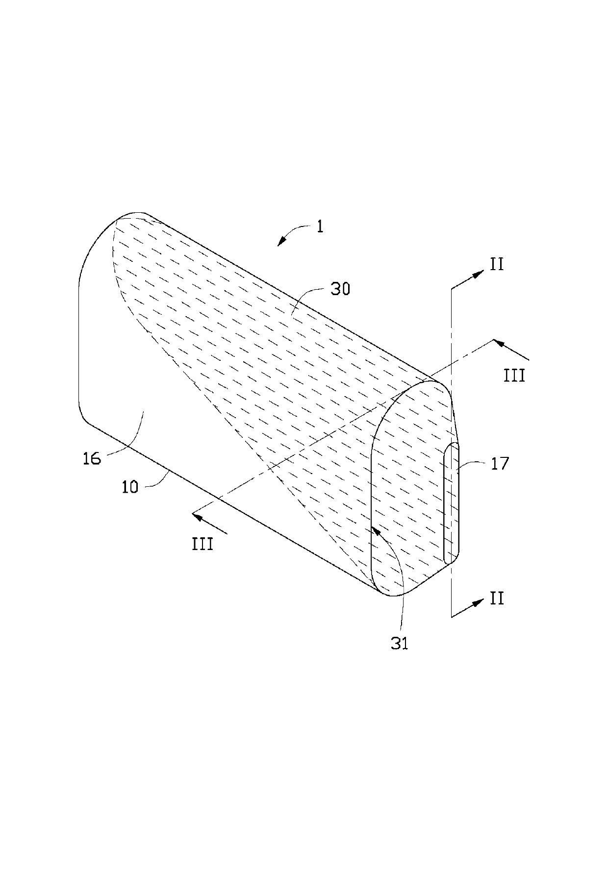
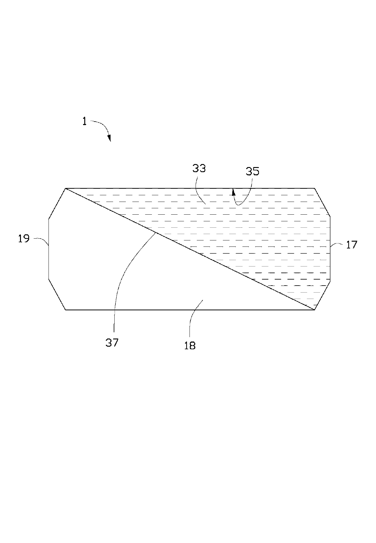
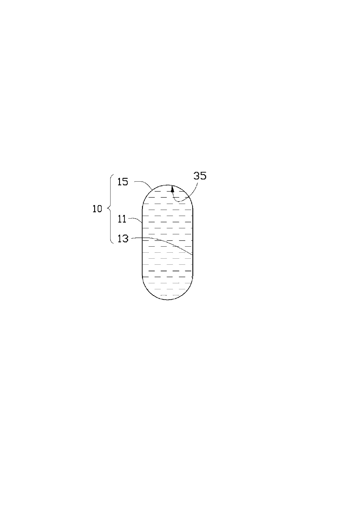
[0023] Such as Figure 1 to Figure 3 Shown is the flat heat pipe 1 of the first embodiment of the present invention. The flat heat pipe 1 includes a shell 10, a capillary structure 30 attached to the inner surface of the shell 10, and a working medium (not shown) contained in the shell 10.

[0024] The housing 10 is made of metal with good thermal conductivity, and includes a longitudinal top plate 11, a longitudinal bottom plate 13 located on one side of the top plate 11 and parallel to the top plate 11, and connecting the top plate 11 and the opposite side edges of the bottom plate 13 The two convex arc connecting plates 15. The opposite ends of the top plate 11 and the bottom plate 13 are flattened to form a first end 17 and a second end 19 that are close to each other, so that the top plate 11, the bottom plate 13 and the two connecting plates 15 together form a sealed containment Space 16. In the longitudinal direction of the flat heat pipe 1, a section extending from the ...


PUM


Abstract

The invention discloses a flat plate heat pipe, which comprises a shell and a capillary structure, wherein the capillary structure is attached to the inner surface of the shell; a steam passage is enclosed by the inner surface of the shell and the surface of the capillary structure together; and the volume of the capillary structure is equal to the volume of the steam passage. Compared with the prior art, the flat plate heat pipe has the advantages that the steam passage of the flat plate heat pipe is positioned on the outer side of the capillary structure, and a working medium which is evaporated from the capillary structure enters the steam passage from one side face of the capillary structure, so that the evaporated working medium has small mutual influence and cannot form turbulent flow easily; and since the volume of the capillary structure is equal to the volume of the steam passage, the maximum heat transfer of the flat plate heat pipe is guaranteed, and the heat resistance is relatively small, and accordingly, the flat plate heat pipe has more superior performance.

Description

Technical field [0001] The invention relates to a heat pipe, in particular to a flat heat pipe. Background technique [0002] At present, heat pipes are commonly used in the industry to solve the high-density heat dissipation problem of high-speed computers, such as heat pipes, loop heat pipes, and flat heat pipes (Vapor Chamber) products. [0003] The working principle of flat heat pipes is the same as that of traditional heat pipes. Because it has a larger heat conduction area than traditional heat pipes and meets the high practical value of "light, thin, short, and small", it is widely used in electronics with larger heat dissipation surfaces. Product. [0004] The traditional flat heat pipe includes a metal shell and a continuous capillary structure evenly attached to the inner surface of the metal shell. The capillary structure includes a steam channel in it. When the flat heat pipe works, the working liquid in the capillary structure evaporates due to heat and enters the ste...

Claims


Application Information

Patent Timeline
Patent Type & Authority Applications(China)
IPC IPC(8): F28D15/04
CPCF28D15/046F28D15/0233
Inventor 代升亮罗友梁
Owner FURUI PRECISE COMPONENT (KUNSHAN) CO LTD
Learn More