Chip mounter detection device

A detection device and placement machine technology, which is applied in the direction of measuring devices, optical devices, instruments, etc., can solve problems such as difficult-to-focus optical identification, placement offset, and impact on visual accuracy, so as to achieve uniform and soft illumination and improve Increased accuracy and brightness

Inactive Publication Date: 2013-09-18
HONG FU JIN PRECISION IND (SHENZHEN) CO LTD +1
View PDF7 Cites 6 Cited by
  • Summary
  • Abstract
  • Description
  • Claims
  • Application Information

AI Technical Summary

Problems solved by technology

However, in the current image acquisition process of patch components, due to the way of illumination (whether it is directly illuminated from above or from the side), it does not take into account that the surface of the patch component may have curvature, which is difficult to focus and the characteristics of optical identification, so that the above-mentioned There will be shortcomings such as uneven lighting or ring light reflections that affect visual accuracy
In addition, the external ambient light where the placement machine is located may also affect the visual accuracy and make the placement position shift, so it is necessary to further study and improve

Method used


Image

  • Chip mounter detection device
  • Chip mounter detection device

Examples


Embodiment Construction

[0011] The present invention will be described in detail below in conjunction with the accompanying drawings.

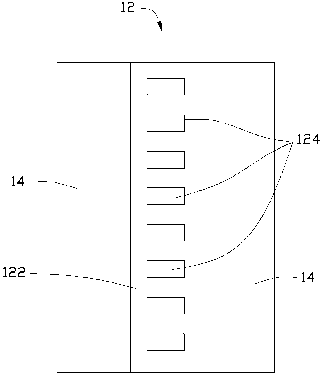
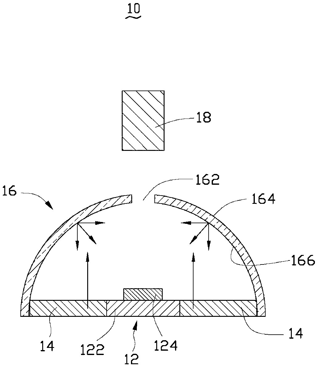
[0012] see figure 1 and figure 2 As shown, a top view of the component to be tested and a light source arrangement of the chip mounter detection device of the present invention, and a side view of the chip mounter detection device of the present invention are respectively provided. The detection device 10 of the placement machine of the present invention includes a component to be tested 12 , a light source 14 , a cover 16 and a camera module 18 . Wherein the component to be tested 12 comprises a circuit board 122 and a plurality of patch components 124, the sticking position of the patch component 124 is predetermined on the described circuit board 122, and the patch component 124 is formed by the patch Machine (not marked in the figure) is pasted on the predetermined pasting position. In this embodiment, the component to be tested 12 is an LED light bar, the ci...


PUM


Abstract

The invention provides a chip mounter detection device, which comprises an assembly to be detected, a light source, a cover body and a shooting module, wherein the light source is arranged on the side edge of the assembly to be detected; the light source is covered by the cover body; the inner surface of the cover body is provided with an atomization reflecting layer; an opening is formed in the upper end of the cover body; the shooting module is arranged above the opening; and the shooting module is used for detecting against the assembly to be detected through the opening. According to the chip mounter detection device, the light source is covered by the atomization reflecting layer of the cover body, so that high-brightness uniform illumination can be provided for the assembly to be detected; and meanwhile, the assembly to be detected is not influenced by external light rays, and the accuracy of the shooting module on the aspect of image alignment detection can be increased.

Description

technical field [0001] The invention relates to a detection device for a mounter, in particular to a detection device for a mounter which can provide uniform illumination. Background technique [0002] As the trend of light-emitting diodes (LEDs) being used as panel backlights takes shape, and LEDs are not only used in small and medium-sized panels, but also develop towards large-sized panels, the packaging and bonding technology related to LED light bars (Light Bar) is relatively important. At present, the manufacture of LED light strips is to stick a plurality of granular LED chips on the strip-shaped circuit board through Surface Mount Technology (SMT). In the surface mount technology, the chip mounter is the key equipment. Mounting accuracy has high standard requirements. Generally speaking, the current placement machine generally adopts the visual centering system to align the placement. The vision centering system is based on the fact that after the placement head abs...

Claims


Application Information

Patent Timeline
Patent Type & Authority Applications(China)
IPC IPC(8): G01B11/00
Inventor 赖志成
Owner HONG FU JIN PRECISION IND (SHENZHEN) CO LTD
Why Eureka
Try Eureka